
1. Introduction
The RTU-300+ platform is a rack-mount Remote Test Unit (RTU), also known as Test Head or Probe, offering telecommunication test resources that can easily scale from single user to multi-user and all the way to centralized proactive network monitoring (PNM) and test systems.
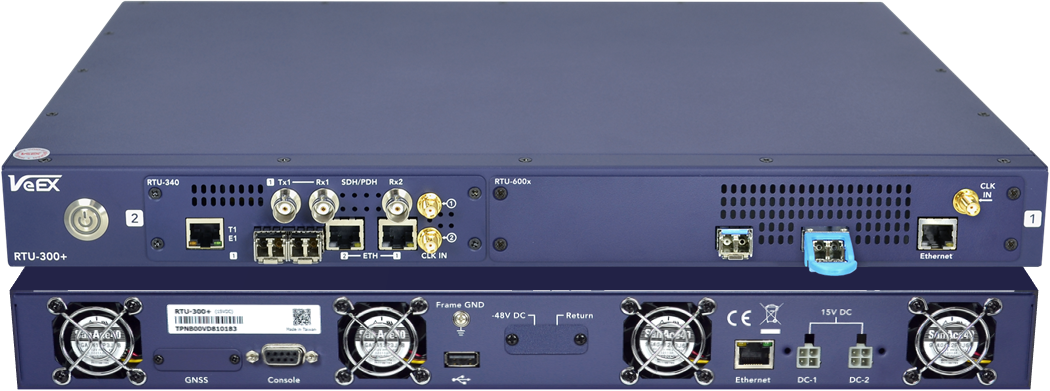
The RTU-300+ may be configured with one or two test modules (e.g., RTU-340 for up to 4x 10G, RTU-600x up to 2x 100G and/or RTU-6400 up to 400G). Each of the test modules may offer up to two test engines (independent test port groups), for a total of up to four fully independent test sessions. It can be used with a single (shared) user interface, multi-user interface or as part of VeSion®, a centralized monitoring and test system, especially when there are limited or no technicians on site (e.g., unmanned point of presence PoP or leased rack space).
This multi-service test head offers performance testing and monitoring of Data Center cross/inter-connect, Head Ends, Metro/Carrier Ethernet and broadband networks from 10 Mbit/s up to 400 Gbit/s. The ideal application of the RTU-300+ is to be used as remote probes under the centralized VeSion® performance testing and monitoring platform, where several RTU-300+ can be added and operated for service provisioning, service activation testing, and service assurance applications.
It can also scale down to meet the needs of simpler applications, smaller operators or budgets, and be operated as a Standalone centralized test instrument, through its built-in VNC/web remote access. In this mode, users have access to additional transmission technologies, interfaces and features, when supported by the RTU modules, from 1.5 Mbps to 400 Gbps, such as EoOTN, OTN, SONET/SDH, PDH/DSn and Fibre Channel.
It can operate in three main architectural modes:
- Standalone/SCPI Mode (Shared) - Single common graphical user interface (GUI) and multi-user access. Users connect to and control individual RTUs. (Formerly known as SCPI mode in older RTU-300). This is the recommended mode for automation applications. That is, using scripts with SCPI commands to control an RTU-300 or RTU-300+ via Telnet or SSH connections.
- Standalone Mode (Multi-User) - Independent multi-test and concurrent multi-user GUI for individual access and control. Users connect to and simultaneously control individual RTUs. (Not available in older RTU-300)
- VeSion® Mode - Ethernet oriented test mode for distributed test heads across the network footprint. This proactive network monitoring and testing mode offers centralized management, control, automation, data collection, analytics, dashboards, etc.
A PDF complete version of this Quick Guide can be downloaded from the RESOURCES section on the RTU-300+ web page.
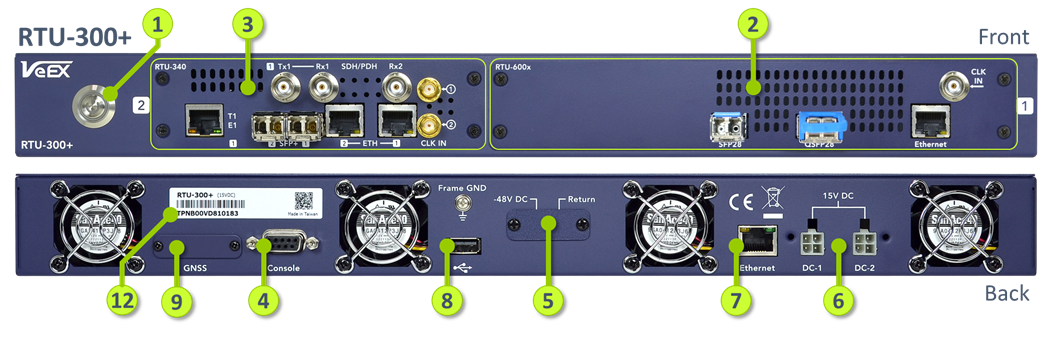
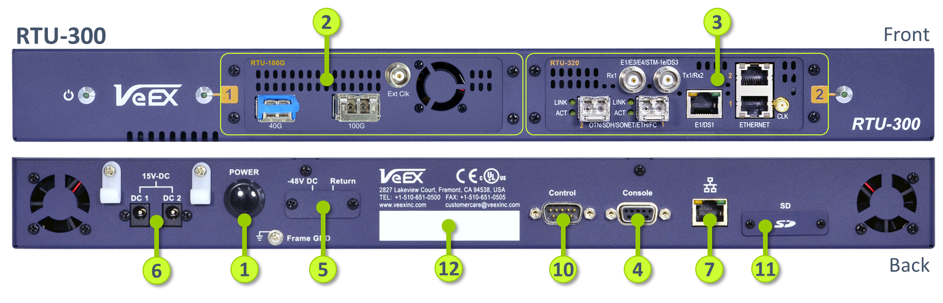
2. Becoming Familiar with the RTU-300+ and RTU-300
-
Power Button
-
Test Module 1 (M1), also known as Slot 1
-
Test Module 2 (M2), also known as Slot 2
-
RS232A Console (serial) port
-
-48 Vdc power input option
-
Dual 15 Vdc power inputs option
-
Ethernet management port
-
USB-A port
-
GPS/GNSS Receiver slot (optional)
-
Control port
-
SD Card slot
-
Serial Number and information label
Note: The improved RTU-300+ replaced the original RTU-300 in 2023. Some of the features and function described in this document may not be available or applicable to older RTU-300 models.
3. Setting Up a New RTU-300+
The initial configuration can be performed via its Console serial port (RS232A) or its BASE-T Ethernet Management port. Ethernet connection is recommended, since no extra software is required. For RS232A connection and configuration information, please refer to the Probe Configuration Tool (User Guide).
3.1 Powering Up
After carefully unboxing the RTU-300+, connect it to the appropriate power source (DC-1/DC-2 or -48V). Verify that the ![]() Power indicator turns red, then press-and-hold the
Power indicator turns red, then press-and-hold the ![]() Power button for about two seconds until you hear one beep (low noise environments) to turn the RTU-300+ ON (solid green light). It will take a few seconds for the RTU to bootup and get ready.
Power button for about two seconds until you hear one beep (low noise environments) to turn the RTU-300+ ON (solid green light). It will take a few seconds for the RTU to bootup and get ready.
The RTU chassis comes in three different power supply configurations:
- Redundant 15Vdc Inputs. This version can be ordered with one or two external universal AC/DC adapters. If ordered with only one adapter, connect it to the DC-1 port.
- Single -48Vdc Input.
- Single -48Vdc High-Power, for 400G applications.
3.2 Ethernet Management Port Configuration
The Ethernet (Management) port, on the back of the RTU, is the main communication port used to access, configure, control and operate individual probes.
3.2.1 Configuring a Brand New RTU Probe
DO NOT CONNECT the RTU to the network (e.g., LAN), until it has been properly configured with a valid IP address.
A brand new RTU can be configured using:
- Web Browser - Direct Ethernet connection to a computer (recommended)
- Probe Configuration Tool - Via Ethernet or RS232A serial cable connection to a computer (Windows™).
This document focuses on the simpler Web Browser method. (You may follow the Probe Configuration Tool link if the IP address of the RTU is unknown.)
To get started, use a Cat5 UTP cable to connect the RTU directly to a PC or laptop.
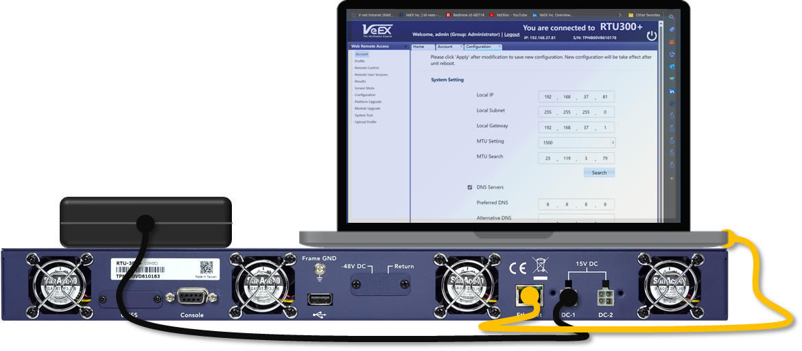
On the PC (Windows, Linux, MacOS), go to the >Settings >Network & Internet >Ethernet configuration and change its LAN port to static (no DHCP) and set its IP address to 192.168.1.200 (use gateway 192.168.1.100 if required).
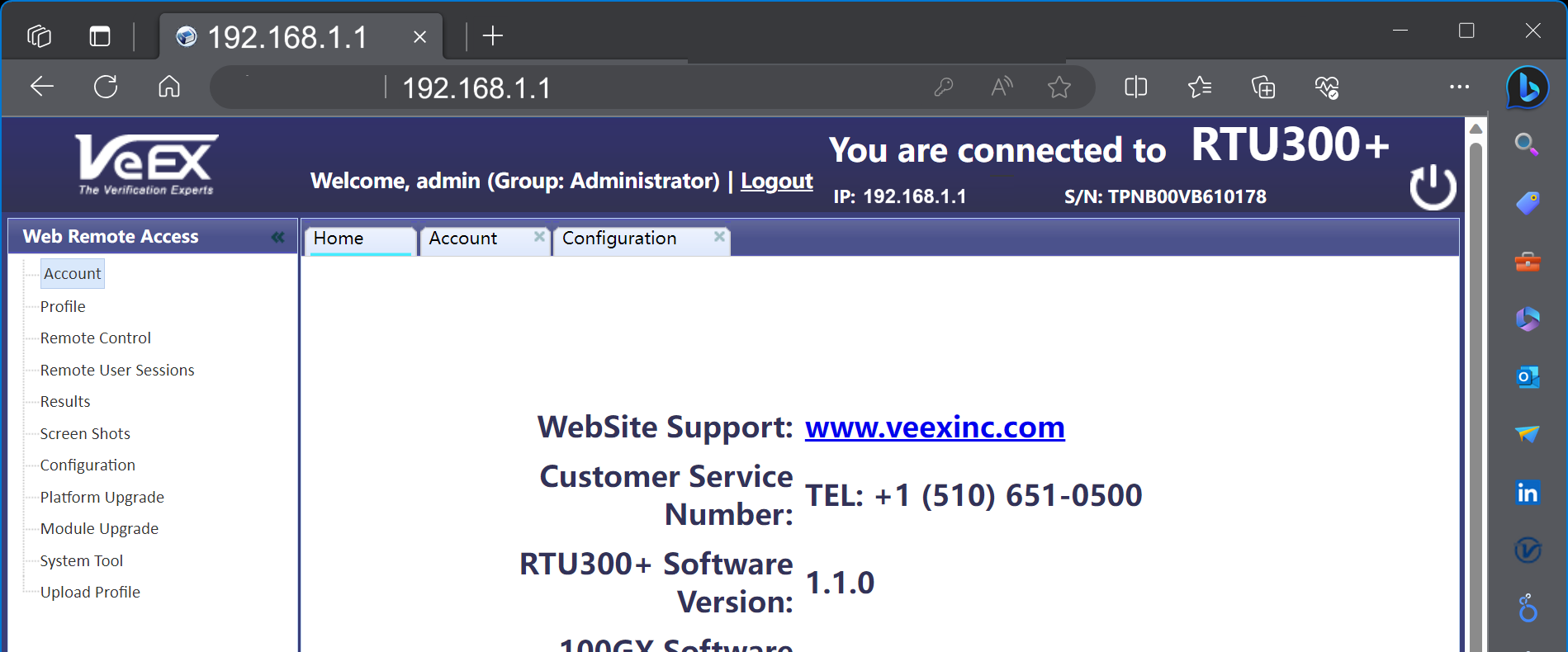
 On the computer, launch a web browser and point it to the RTU's IP address. By default, the RTU will have the following static IP address assigned from the factory: 192.168.1.100 (the default for older RTU-300 was 192.168.1.1)
Login using the admin User ID and default veexinc password.
Security Warning: It is highly recommended to change the RTU's temporary default passwords before connecting the RTU to the network or giving it any access to the Internet.
The RTU-300+ Home page should open, presenting basic information about the probe and the Web Remote Access menu. Any of these functions that are opened will remain as a tab on the top bar, until manually closed, so they are easily accessible. Certain files may also open as new tabs.
Change the admin credentials: On the Web Remote Access menu, click on Account and start by selecting the check box for the default admin user, click on Edit, change the Password and click on OK. At this point, you may also elect to Add new Administrators or other Regular users. Note that User Names or User IDs are case sensitive and can include spaces.
Select Configuration from the Web Remote Access menu and use the System Settings section to setup the local network connection parameters for the Ethernet management port (on the back) of this RTU probe: Local IP, Local Subnet, and Local Gateway IP addresses.

For NETWORK SECURITY reasons, the use of unprotected public IP addresses for the RTU's management port (Local IP) is not recommended! Damages and downtime related to hacking, malware, attacks, infections, etc., are not covered by the product's warranty.
If required, enter the desired Maximum Transmission Unit value on the MTU Settings field (the default value is 1500). In the MTU Search field you may also enter the IP address of a server (e.g., VeSion) on the target network, from which the RTU will be controlled, then click on Search to perform an automatic calculation of the optimal value for that particular end-to-end network path.

Do not enable the DNS Server (Domain Name Server) as it is not needed for standalone mode. Leave its IP addresses fields blank or at its default value.
In the RTU300+ Settings section, the suggestion is to leave the RTU in Standalone mode, while getting familiar with the instrument, and before enabling the multi-user capabilities or adding it as a probe to a centralized VeSion™ monitoring system.
Press Apply.
The new IP changes will become effective after the next reboot. Turn the RTU OFF, using the ![]() Power button, or use the soft
Power button, or use the soft ![]() Reboot button on the top-right corner of the browser page.
Reboot button on the top-right corner of the browser page.
Connect the RTU's Ethernet management port (on the back of the chassis) to the LAN and turn the RTU ON.
Reset the computer back to its standard IP settings (e.g., DHCP), connect it to the LAN/WLAN, point the browser to the RTU's newly assigned IP address and login. Once a successful connection is confirmed, you may continue with the rest of the configuration, add new users, attach the side brackets and then install the RTU onto a 19" rack.
3.2.2 Reconfiguring Existing RTU Probes
If the RTU IP address and passwords are known, use a web browser to access the Web Remote Access page and make any necessary changes as explained in the other sections of this guide.
- Don't Remember/Know the Probe's IP Address? The simplest way to get the IP address of an RTU-300+ is by connecting a terminal emulator to the RS232A Console port, configured at 115200 bit/s, 8-bit data, 1 stop bit, no parity. Turn the RTU ON and look for the following IP configuration command at the end of the bootup log:
- cmd:ifconfig eth0 192.168.37.81 netmask 255.255.255.0
-
Forgot (or Don't Have) the Password? Download VeEX's Probe Configuration Tool application for Windows™, from the RESOURCES section of the RTU-300+ web page. It can also be downloaded from www.veexinc.com >Support >Software Updates, by entering the first four characters of the RTU's serial number (e.g., TPNB), and clicking on Submit to get a list all applicable software available. On the Probe Configuration Tool line, click on the link with the Version number to download the installer package and on the PDF link to download the release notes for information.
Unzip the Probe Configuration Tool (no installation required), then connect the PC to the RTU's Console port (using an RS232A or USB-to-RS232A cable) and follow the instructions from the Probe Configuration Tool for RTU-300+ (Quick Guide), or the PDF guide available on the RTU-300+ web page.
Alternatively, if the VNC password is known (or if it was left as the default pass1), connect to the test set using any standard VNC client and follow the Reset RTU-300+ procedure below. - Reset RTU-300+. If instructed by a Customer Support agent, point a web browser to the RTU's IP address, to access the Web Remote Access page, select Remote Control and enter the VNC password (default is pass1). On the RTU-300+ GUI, go to >System Tools >Files >Manage, click on the Format button, then on YES and YES. The RTU will retain its current IP configuration, however, all files, configurations (Profiles) and user accounts will be deleted, and all passwords are reset to factory default, including the admin.
3.3 Software Updates
Note that the software update is an intrusive process and any active test session(s) will be terminated. Make sure to save any configuration or test results before proceeding. Also, the RTU must remain powered during the software update process.
3.3.1 Applying Software Updates Using a Web Browser
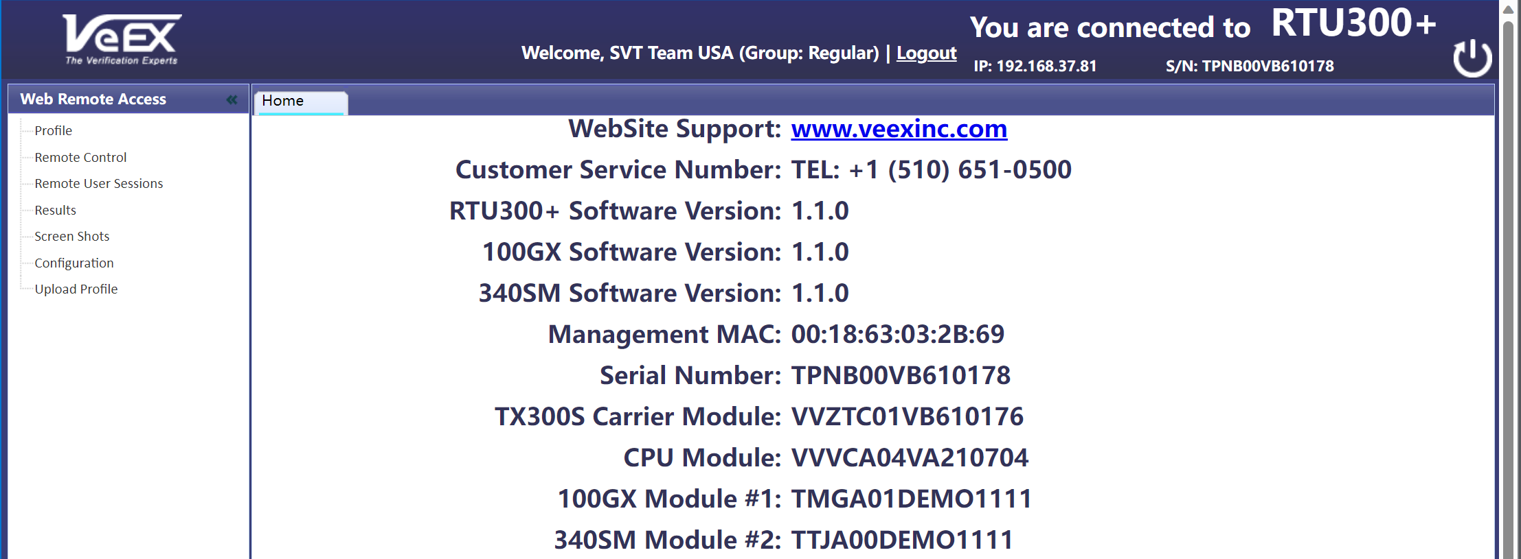
The software version numbers, currently installed in the RTU, are displayed on the Home tab of the Web Remote Access page.
Download any required installation packages:
- Check the RESOURCES section of the product's web page for newer platform and test module(s) software releases.
- You can also go to www.veexinc.com >Support >Software Updates, enter the first four characters of the RTU's serial number (e.g., TPNB), and click on Submit to get a list all applicable software available.
There are individual installation packages for the platform and each test module type. If newer versions are available, download the required packages to a PC (Win, Mac, Linux) and follow the installation instructions.
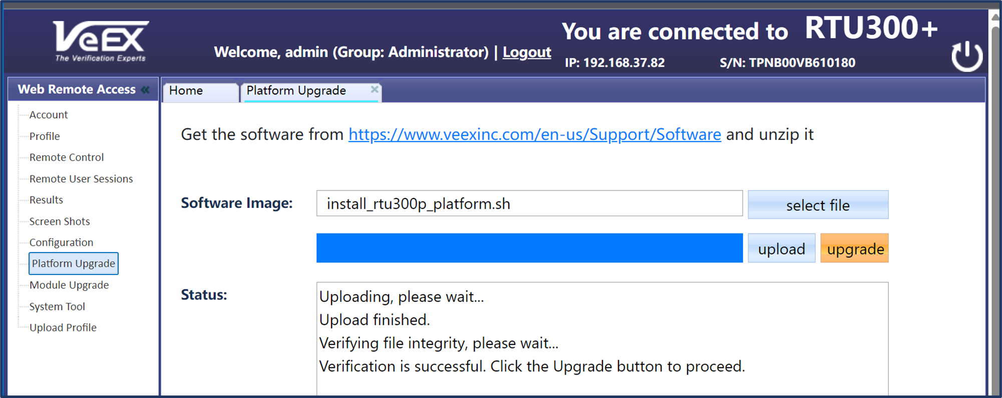
- Unzip the downloaded files. The resulting installer packages' file names have the following format: install_rtu300p_*******.sh
- On the Web Remote Access menu, select Platform Upgrade.
- Click on Select File and navigate to the install_rtu300p_platform.sh file.
- Once the install package is validated, click on the Upload button.
- When the install package finishes uploading to the RTU and passes the error check, click on the Upgrade button.
- Click Yes on the pop-up to acknowledge that the RTU-300+ will reboot to start the software update process.
- The RTU will reboot, and all active users will lose access during the software update process. The process will take a few minutes.
- The Status field will show the progress of the software update process.
Once the platform update process has finished, the test module(s) software must be updated. Login again and repeat a similar process for each of the different test module types installed in the RTU, using the Module Upgrade function and the install_rtu300p_<module>.sh files. If the RTU has two modules of the same kind, the module update should only be performed once (e.g., RTU loaded with two RTU-340 modules).
Tip: Multiple RTUs can be upgraded at the same time, using this method. Just open a new browser tab for each of their IP addresses and follow the procedure in parallel. The browser should remember the location of the software image file.
3.3.2 Applying Software Updates Using a USB Memory Stick
As an alternative, the RTU platform and its test module(s) software can also be updated by using a USB memory stick:
- Copy the unzipped platform and module(s) installer packages to the root of a USB memory stick.
- Insert it into the USB-A port on the back of the RTU.
- Turn the RTU ON.
The installer package will be detected during the bootup process and applied to the system first, then to each of the test modules. During the software update process, the ![]() Power indicator will blink green. The RTU may reboot multiple times during the process.
Power indicator will blink green. The RTU may reboot multiple times during the process.
Users can also monitor the bootup and software update process by connecting a terminal emulator to the RS232A Console port, configured at 115200 bit/s, 8-bit data, 1 stop bit, no parity.
Once the software update is completed (solid green power button), verify the version numbers displayed on the Home tab of the Web Remote Access page.
3.4 Setting the System's Date and Time
3.4.1 Manual Setting
In Standalone mode, point a web browser to the RTU's IP address, login, select Remote Control and enter the VNC password to access the RTU-300+ GUI.
Go to ![]() System Tools >Utilities >Settings >Date & Time, to manually set the date, time and time zone.
System Tools >Utilities >Settings >Date & Time, to manually set the date, time and time zone.
To enable daylight saving time (DST), manually select a neighboring time zone with a +1:00 relative to the standard time zone of the current location. Set it back to the standard time zone offset when DST ends. (e.g., in California, standard time is UTC-08:00 and DST is UTC-07:00.)
3.4.2 NTP Server
For automatic time of day (ToD) synchronization, go to ![]() System Tools >Utilities >Settings >Global >General Settings, and enable the NTP Time Services field by selecting a synchronization period (e.g., 1 hour). Enter the URL for your organization's official NTP server or click on the following link for a list of local, regional and global public NTP servers.
System Tools >Utilities >Settings >Global >General Settings, and enable the NTP Time Services field by selecting a synchronization period (e.g., 1 hour). Enter the URL for your organization's official NTP server or click on the following link for a list of local, regional and global public NTP servers.
3.4.3 Getting Standard Time from GPS/GNSS
If equipped with the GPS/GNSS receiver (hardware option), users can also manually copy the GPS time into the system. Go to ![]() System Tools >Utilities >Settings >GPS/High Precision Clock, to Configure the GNSS Receiver and turn it ON.
System Tools >Utilities >Settings >GPS/High Precision Clock, to Configure the GNSS Receiver and turn it ON.
Once it recovers time (ToD UTC) from the satellites, click on the Sync ToD button to apply the standard time to the RTU. The standard time will be applied at the start of the next second (rise of the internal 1PPS timing signal).
The local UTC Offset (Time Zone) setting is used to apply the correction for local time. This manual Sync ToD time setting function should not be used when NTP is enabled.
4. Standalone Operation Mode
The Standalone mode is intended to offer local and/or remote control to manage individual RTU test heads (e.g., lab, local network, node, unmanned point of presence, etc.). In this mode, an RTU acts as a single instrument, offering multiple test resources, which can be managed/controlled by one or multiple users, via Web Browser or VNC client. Users can still have access to multiple RTUs by establishing individual sessions to the specific IP address of each probe.
To configure the RTU for Standalone operation, point the web browser to the RTU's IP address, go to the Web Remote Access menu, select Configuration, and under the RTU300+ Settings set the Operating Mode to Standalone.
4.1 User Types (User Groups)
The RTU can support multiple user accounts, who can share the platform's test resources (up to four independent tests, depending on hardware configuration). Each user has their own individual login credentials. Users are defined for individual RTUs.
- Administrator - Administrators can create and delete users, as well as reserve test resources, configure test interfaces, run tests, view results, and manage test reports. They can also access, modify, terminate and release tests sessions created by other users.
- Regular - Regular users can reserve test resources, configure test interfaces, run tests, view results, and manage test reports. Regular users can only release their own test sessions (those they have created).
To manage users, select Account on the Web Remote Access menu and use +Add to create new users, or check the box of an existing user to configure:
- User Group - Assigns Administrator or Regular privileges to the User Name account. To move an existing user from one group to the other, the account must be deleted and created again.
- User Name - This User ID is case sensitive and accepts spaces, to allow using the person's name as proper identification.
- Password - Alphanumeric password for the User Name account.
4.2 Web Remote Access UI and the RTU-300+ GUI
This document makes reference to two nested user interfaces on the web browser client:
- Web Remote Access UI - Besides providing a user validation layer and basic probe information, the left menu of this User Interface provides access to basic RTU platform (a.k.a. chassis or system) configuration, management features and access to data. This is accessible by simply pointing a web browser to the RTU's IP address and entering valid user credentials.
- RTU-300+ GUI - This Graphical User Interface appears when the Remote Control feature is launched from the Web Remote Access menu or when using a VNC client. This shared GUI allows users to manage, configure and operate individual test sessions running on the RTU's test ports. It also allows access to some extra platform features in the
 System Tools menu. The RTU-300+ GUI is available in standalone and multi-user modes (not available in VeSion mode).
4.2.1 Web Remote Access Menu
 Account – Manage user accounts. Add, Edit or Delete users' credentials (user ID and password).
- Profile – Manage test profiles. Test Profiles are commonly used configurations, saved by users, that can be retrieved and reapplied to a test session. For example, commonly used configurations and test limits/threshold can be saved as test profiles, for different types of services.
- Remote Control – Access the shared RTU-300+ GUI (graphical user interface). Start test sessions, configure tests, run tests, view results, save results, etc. Default password is pass1 and it can be changed using the RTU-300+ GUI and going to System Tools >Utilities >Settings >Remote Access.
- Results – Manage test results (view, generate PDF, download to PC, delete, etc.)
- Screen Shots - Manage screen shots taken from the RTU-300+ GUI. To enable the GUI screen capture feature, use the RTU-300+ GUI to go to System Tools >Utilities >Settings >Global >Save Settings, and set Lock/Save Screen to Save Screen. The use of PNG format with No Compression is recommended. When the Remote Control tab is selected, use the link under Shortcuts (on the Web Remote Access menu) to capture and save the current GUI being displayed.
- Configuration – Configure system settings such as Local IP address, Subnet, etc., as well as other RTU-300+ settings, such as the main Operating Mode to select whether the probe is operated via VeSion or Standalone (web browser or VNC).
- Platform Upgrade – Allows administrators to perform platform software updates. Download the installer files from the Resources section on the RTU-300+ website. Always update the platform first, then each of the modules.
- Module Upgrade – Allows administrators to perform modules' software updates. Download the installer files from the Resources section on the modules' website.
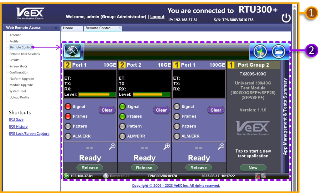
- System Tools - Allows remote rebooting of the RTU. This can also be accomplished by clicking on the
 Reboot icon on the top-right corner of the web page.
 - Upload Profile - Users can upload test profiles files from the PC, created with the ReVeal RXTS PC application or copied from other RTUs.
4.2.2 Basic RTU-300+ GUI Navigation
![]() Use the System Tools button to access extra platform/system related settings, utilities, functions and tools.
Use the System Tools button to access extra platform/system related settings, utilities, functions and tools.
![]() Click on the Test Cards & Summary button to view all test resources, launch new test applications, switch between active tests or release test resources.
Click on the Test Cards & Summary button to view all test resources, launch new test applications, switch between active tests or release test resources.
![]() Use the Home button to return to the current Test Application or System Tools Main Menu.
Use the Home button to return to the current Test Application or System Tools Main Menu.
![]() Use the Exit button to go back to the previous menu level or exit a function.
Use the Exit button to go back to the previous menu level or exit a function.
![]() Shows basic information about the current test application being displayed on the GUI, such as Module Number (orange), Port Group Number and Test Application type. Click on this button to access the Test Mode Selection menu for the current test session, where users can change the physical test interface type, transmission protocol, test mode or release the test resource.
Shows basic information about the current test application being displayed on the GUI, such as Module Number (orange), Port Group Number and Test Application type. Click on this button to access the Test Mode Selection menu for the current test session, where users can change the physical test interface type, transmission protocol, test mode or release the test resource.
4.3 Remote Control - Web Remote & VNC Clients
By default, the RTU is configured to provide a common graphical user interface (GUI) for all users, with shared controls. In this mode, the RTU can still offers up to four test resources, up to four independent tests and simultaneous multi-user access. However, the tests are all controlled by one user interface (all users see and interact with the same test GUI).
4.3.1 Web Remote Control
Launch a standard web browser (from a computer, tablet or smartphone), point it to the RTU's IP address and enter the user credentials (valid username and password). From the Web Remote Access menu on the left, select Remote Control, and enter the VNC password to gain access to the RTU-300+ GUI.
The default VNC password is pass1 (change it as soon as possible). External/remote users may need VPN to access the same LAN segment of the RTU.
4.3.2 VNC Client
Launch the VNC client of your choice (also known as VNC Viewer), enter the RTU's IP address and the VNC password.
The default VNC password is pass1 (change it as soon as possible). External/remote users may need VPN to access the same LAN segment of the RTU.
Security Warning: The temporary default VNC Passwords must be changed before connecting the RTU to the network or give it access to the Internet.
Once connected to the RTU via remote control (VNC or browser), go to ![]() System Tools >Utilities >Settings >Remote Access and enter unique VNC Super User Password and VNC Regular User Password in their respective fields.
System Tools >Utilities >Settings >Remote Access and enter unique VNC Super User Password and VNC Regular User Password in their respective fields.
4.3.3 EZ-Remote™
Offered free of charge, the EZ-Remote cloud service allows remote users (off premises) to access RTUs over the internet, offering similar functionality as the Web Remote Control, with global coverage (no VPN required). To activate the EZ-Remote service, go to ![]() System Tools >Utilities >Settings >EZ-Remote on the RTU-300+ GUI, follow the instructions and then notify the remote user(s). No user information or registration required. Once activated, the
System Tools >Utilities >Settings >EZ-Remote on the RTU-300+ GUI, follow the instructions and then notify the remote user(s). No user information or registration required. Once activated, the ![]() indicator is displayed on the bottom status bar of the RTU-300+ GUI.
indicator is displayed on the bottom status bar of the RTU-300+ GUI.
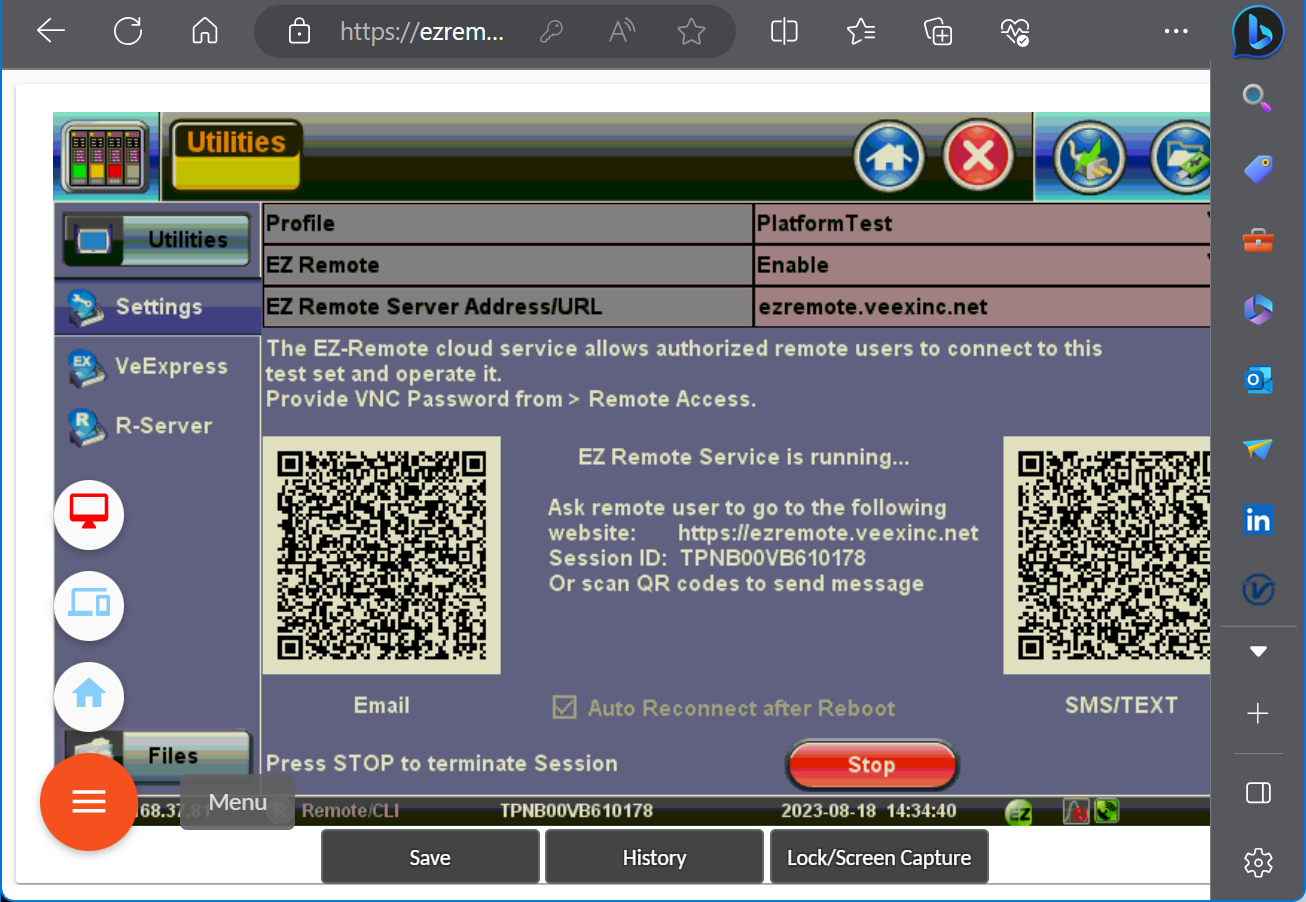
For more information, refer to this EZ-Remote Guide.
4.4 Common RTU-300+ GUI & Test Cards
In basic Standalone mode, all users share the same RTU-300+ GUI, so only one person at a time should take control of it. This is only recommended for applications with a very small and controlled user group within the same office, floor or premise (e.g., equipment room, lab or NOC) in which one person is in charge.
The Test Cards GUI is the main point of entry to all test resources (test ports) and a common place to manage all test sessions and test resources. The number of test cards displayed varies depending on the number of test modules installed, the number of test port groups or how many independent tests each module can support. For physical test port identification, the module number is displayed in orange and the port groups in white.
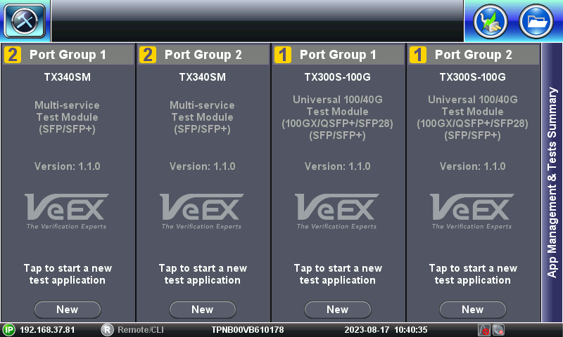
Click on the New button to reserve the required test resource and initiate a test session.
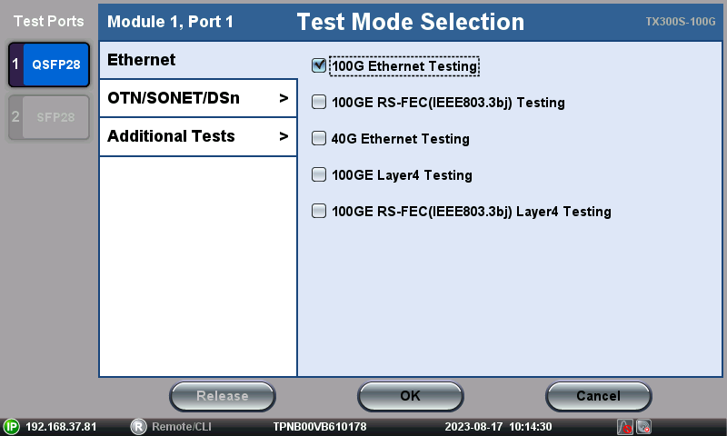
On the Test Mode Selection menu, select the appropriate physical port from the available Test Ports in that group, then choose from the list of transmission technologies supported by the selected test port and launch the desired test application.
 When in the System Tools menu or wanting to switch between test sessions, click on the
 ![]() Test Cards summary button (on the top-left corner of the GUI) to access the App Management & Test Summary screen.
Test Cards summary button (on the top-left corner of the GUI) to access the App Management & Test Summary screen.
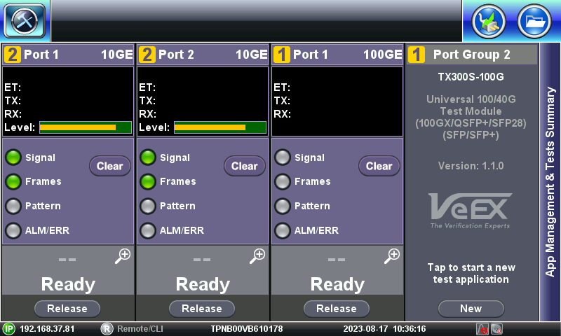
Click anywhere on a test card to join an active test session or click on the Release button to terminate a test session and make its test resources available to others and/or to change test modes, test interfaces and/or technology.
If one of the test resources is assigned to and being used by an external script, for automation purposes, the reserved test Port Group will display the SCPI test card. Local or remote users can't view, interfere with or release the SCPI-based scripted test session. SCPI should only be used in basic Standalone mode (without multi-user).

4.5 Multi-User & Multi-test Environment
The Multi-User mode is still considered a Standalone operation, since all the users still interact with and operate individual RTUs. The advantage is that each active user gets an individual GUI to manage their own test session(s). This makes its operation easier for relatively large and disperse groups working from the premises or remote locations (e.g., building, data center, campus, metro, NOC, remote PoPs, small operators, rural applications, etc.). This is still a hands-on approach. For larger applications (coverage) requiring multiple RTUs, test data consolidation, analytics and reporting, refer to the VeSion mode.
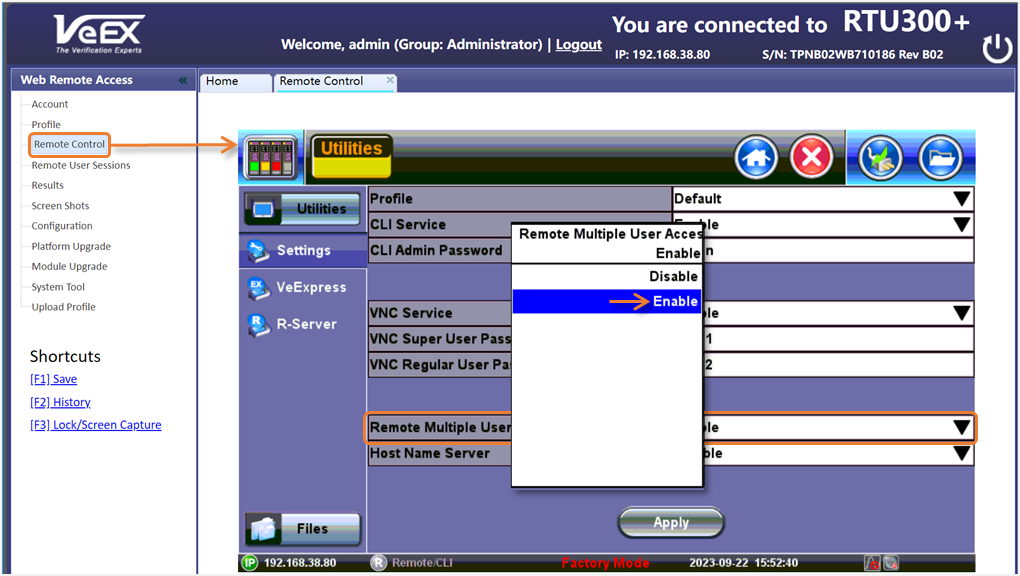
When enabled, users can concurrently share the RTU's test resources (port groups), using independent test sessions, with dedicated user interfaces (users' sessions don't interfere with each other). To enable it, use the (web) Remote Control function or a VNC client to access the common RTU-300+ GUI. Then go to ![]() System Tools >Utilities >Settings >Remote Access, enable Remote Multiple User Access and press Apply. The RTU needs to reboot for the change to take effect.
System Tools >Utilities >Settings >Remote Access, enable Remote Multiple User Access and press Apply. The RTU needs to reboot for the change to take effect.
Once enabled, the active test sessions and available test resources can be monitored and managed from the Remote User Sessions page (replacing the Test Cards).
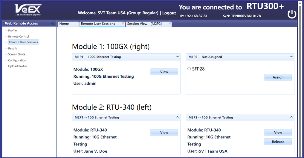
Each session clearly identifies each of the test resources, so other users can identify the active test sessions, who is using each test port, and which ones are available.
- Module Number: Module 1 or 2 (M1, M2).
- Module Type: e.g., RTU-340 (16G), RTU-600x or 100GX (100G), etc.
- Module Position: Left or Right. Physical position of the module on the front panel.
- Port Group: Port Group 1 or 2 (P1, P2). The port groups are also referred with the M1P1 notation, to indicate "Module 1, Port group 1".
- Test Mode: Test Mode loaded on each of the active/busy test resources ("Not Assigned" for any available/idle resources).
- User ID: User Name of the person using that test port group (test resource).
The test session initiation process is similar to the one for the (VNC) Remote Control, with the difference that each user gets a dedicated GUI for each test session. That is, up to four users can work concurrently on the same RTU, without interfering each other.
To start, point a web browser to the RTU's IP address and login.
On the Web Remote Access menu, go to Remote User Sessions, select a Test Port Group, select the required physical test interface (test port), click on Assign to reserve it.
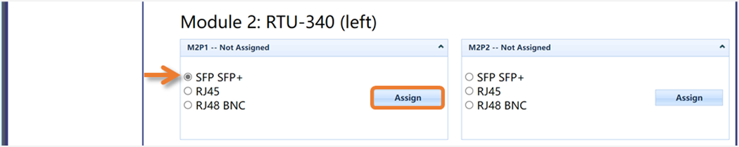
Expand the applicable transmission Technology menu (e.g., Ethernet), select the appropriate Test Mode (e.g., 10GE testing), then click on Submit.

A “Starting test application, please wait…” message will appear, while the application loads. The amount of time varies depending on the test module and test application selected.
For active tests, any authorized user can click on the View button to enter a particular test, as a guest.
When finished, the owner of the test (and administrators) can click on the Release button, to terminate a test session and make those test resources available to others.
When the Multi-User environment is enabled, users must use the Remote User Sessions menu to access active tests and available test resources. Direct access to tests via VNC, Web Remote Control or EZ-Remote will not be available (only limited access to the System Tools menu).
5. VeSion - Adding RTU-300+ to a Monitoring System
In summary, VeSion is a centralized, distributed or cloud system that uses a server (group of servers or cloud) to control multiple geographically dispersed RTUs (and portable field test equipment), gather results, correlate data and build a comprehensive view of the health of the network and services. RTUs can be used to run tests on demand (triggered by events or job orders) or to proactively monitor the health of links (scheduled tests), etc. VeSion mode focuses on testing modern Ethernet & IP interconnect, metro, edge and access network fabrics.
Multiple RTU-300+ can be integrated to and controlled by VeSion, a centralized test, monitoring, workflow and data management system. This requires a VeSion system, servers/cloud, main license, user licenses, RTUs, etc.
This section focuses only on the RTU-specific settings required to establish a connection with the VeSion system, so VeSion administrator(s) can take control of the RTU and integrate it into the company's org chart and processes.
Note: Certain test modules may not be initially supported by the VeSion system. Check the latest software release notes for updates.
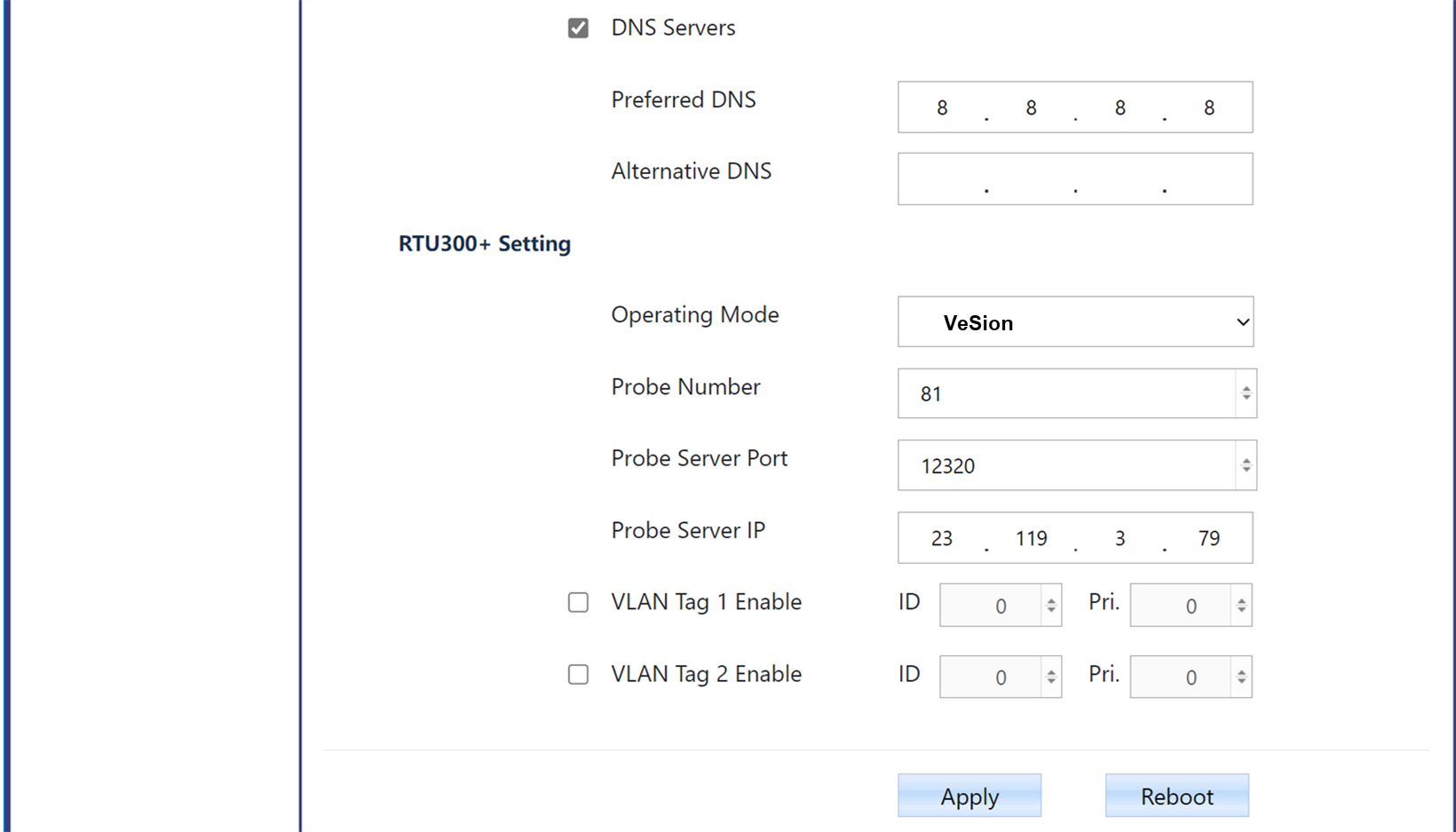
- Probe Number: Enter the remote probe number assigned by the VeSion system administrator, for this particular RTU.
- Probe Server Port: The TCP port number used to establish communication with the VeSion server. Unless instructed otherwise, use 12330 for RTU-300+ or 12320 for older RTU-300.
- Probe Server IP: Enter the IP address of the VeSion server to which this RTU has been assigned to.
- VLAN Tags: Up to two VLAN tags can be added. Use the checkboxes to enable, if required.
- VLAN ID - Specifies the VLAN to which the frames belong. It is a 12-bit field with values of 0 and 4095 (0x000 and 0xFFF).
- VLAN Priority Point Code (PCP) - Refers to the IEEE 802.1p Class of Service (CoS) which indicates the frame priority level. Different PCP values can be used to prioritize different classes of traffic.
Web Remote, VNC or EZ-Remote access to local GUI are not available in VeSion mode.
For further details, refer to Introduction to RTU-300+ VeSion Mode (Quick Guide).
About the RTU-300+ and RTU-300 Platforms
The RTU-300+ platform, an evolution of the RTU-300, was introduced in 2023. It replaced the RTU-300, offering important improvements:
- Easily accessible front Power button and power status indication.
- Locking DC connectors (DC-1 and DC-2).
- More powerful AC/DC adapters (capable of supporting 400GE applications).
- Improved cooling system (capable of handling 400GE applications).
- Improved test modules' fastening for better serviceability.
- Added USB-A port (local data transfer, backup/restore, software updates, etc.)
- Added GNSS Precision Timing Receiver slot (hardware option).
- Improved Standalone with added Multi-user operation.
- Support for RTU-340, RTU-600x and RTU-6400 modules expand its present and future test capabilities and test resources availability.
- Fully independent test port groups (test engines), capable of up to four concurrent tests.
- Upgraded multi-core CPU for more platform processing power and system features.
- And much more...
With up to two factory-installed test modules (hardware options) and license-oriented field-upgradeable features allow flexibility to fit any additional application at a later time. For example, the addition of Fibre Channel or OTN options. Available in -48 Vdc version or Redundant 15 Vdc power supplies, in a space efficient 1U rackmount chassis format. With its built-in dual power switching matrix, it ensures continuous operation if one of the external AC/DC power supplies fails.
RTU-320 Test Ports (RTU-300 chassis only)
- 2 x SFP+ for Ethernet, Fibre Channel, OTN & SONET/SDH
- 2 x RJ45 for Ethernet
- 2 x BNC for E1, E3, E4, DS3, STM0/STS1, STM1/STS3
- 1 x RJ48 for E1/DS1
- 1 x SMA for External Clock Interface
RTU-340 Test Ports (RTU-300+ chassis only)
- 2 x SFP+ for Ethernet, Fibre Channel, OTN & SONET/SDH
- 2 x RJ45 for Ethernet
- 3 x BNC for E1, E3, E4, DS3, STM0/STS1, STM1/STS3
- 1 x RJ48 for E1/DS1
- 2 x SMA for External Clock Interfaces
RTU-600x Test Ports
- 1 x QSFP28/QSFP+ for 100GE, 40GE and OTU4
- 1 x SFP28/SFP+ for 25GE (10GE and 1GE in single RTU-600x configurations only)
- 1 x RJ45 for Ethernet (single RTU-600x configurations only)
- 1 x SMA for External Clock Interface