
A poor optical connector mating will compromise OTDR measurement accuracy by causing excessive insertion loss, high initial reflectance, or both. Modern fiber optic connectors typically use ultra physical contact (UPC) or angled physical contact (APC) end-face finishes, with APC connectors polished at an 8-degree angle.
-
Properly mated APC connectors typically have an insertion loss of 0.14 to 0.25 dB and reflectance (back reflection) between -60 dB and -65 dB. APC has become the preferred choice for SMF OTDRs.
-
Properly mated UPC connectors typically have an insertion loss of 0.1 to 0.3 dB and reflectance between -50 dB and -55 dB.
Poor initial connection (at the instrument's test port) can result from a damaged or contaminated connector end face, a loose internal connector, a test port coupler with a weak spring lock or cracked ceramic sleeve, or a damaged universal adapter. Although less common, similar symptoms may indicate a faulty laser or damage to an internal coupler or splice. Any of these issues can compromise OTDR performance and measurement accuracy.
What Does It Look Like?
The specific effects on the OTDR trace will depend on the type of connector mating issue, the OTDR settings, and the fiber link under test. The example below compares two traces for the same fiber link: one showing a good initial connection and another showing a poor connection mating at the test port, with high reflectance and high insertion loss.
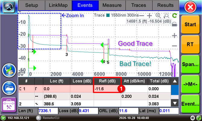
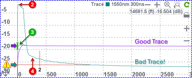
Zooming in on the beginning of the trace (highlighted in blue) reveals key details that help identify problems with the initial connection:
-
The measured reflectance value at event 1 (OTDR's test port). The initial reflectance is -11.6 dB which is very high considering this has an APC polish connector expecting a reflectance value less than -60 dB.
-
Visual representation of the (high) initial -11.6 dB reflection.
-
The green bar on the y-axis is a visual guide for where the user should expect a good initial linear backscatter to be measured for the specific test parameters chosen. The purple trace shows linearity within the green bar, so it is considered to have a good mating, hence it shows the full trace, with the correct end of fiber.
-
The teal trace shows bad linearity because the back-extrapolation of the linear backscatter falls far below the expected green bar range. As a result, the actual end of fiber cannot be identified since the trace drops into the noise.
Let the Instrument Help You
There are two ways to know whether your fiber connection is good, poor or outright bad:
-
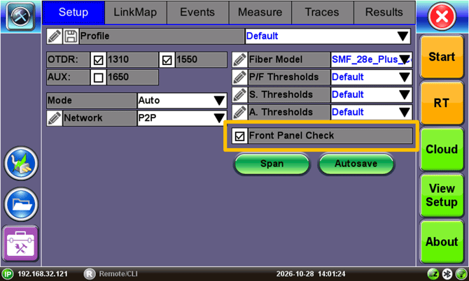
Method 1 - VeEX OTDRs include a Front Panel Check feature that automatically alerts users when the initial Scatter level is lower than expected or the initial connection’s Reflectance is worse than -45 dB.
-
Method 2 - Zoom IN on the beginning of the trace (as shown earlier) to verify that the Linear Scatter level (dB/km) falls within the green Launch Level bar shown on the vertical axis. Then check the Events Table to confirm that the initial connector’s reflectance meets the expected value for its polish type (UPC or APC).
Mitigation & Prevention
Besides regular cleaning and inspecting, one option to prevent optical test port damage is to use instruments with sacrificial Optical Connector Protector or "connector saver" systems, which allow users to replace the working (exposed) end-face when/if it gets damaged, without having to send the test set back to factory or authorized service center for lengthy and costly repair and re-calibration. These small sacrificial connector extenders protect the internal calibrated end face from the environment, regular use, abuse and accidents.