
The upstream In-Channel Frequency Response (ICFR) is an important diagnostics tool. Being able to view the frequency response measurement of an Upstream Channel is an insightful troubleshooting feature for legacy DOCSIS SC-QAM UCDs (available in all VeEX CX-series of DOCSIS 3.1 meters). This feature is important to cable operators working on Extended Spectrum DOCSIS (ESD) and Upstream expansion, with Mid-Split (to 85 MHz) and High-Split (to 204 MHz) upgrades, for tuning HFC networks into offering competitive Internet upload speeds.
How Does It Work?
- The CMTS constantly monitors the quality of the signals it receives from far end cable modems and can determine if the signal is impaired with frequency response issues such as tilt and roll-off (e.g., the yellow spectral channel trace, below).
- Then, the CMTS can ‘instruct’ the affected cable modem(s) to pre-equalize or pre-distort its transmitted signal to counter the effects of those impairments, by inverting its transmit signal properties (e.g., red dotted line). The effect is that the signal received by the CMTS is in a more ideal flat state, even after being degraded (e.g., green dotted line).
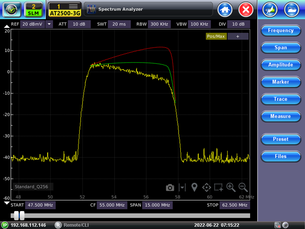
Based on this received signal, the CMTS will instruct the affected Cable Modem to transmit an over-compensated signal (red), to account for the impairments it will encounter in the HFC network. Here is an example of the pre-equalized signal transmitted by the cable modem:
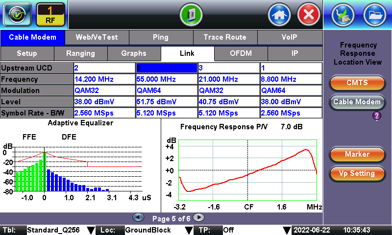
Within the ICFR measurements, the Peak to Valley (P/V) value provides a good indication of signal quality. Ideally, the P/V value is flat across the entire channel bandwidth. A typical PASS threshold is <3 dB, so the above example would be considered a 'FAIL'.
Note that when CMTS pre-equalization is used to compensate for a poor signal(s), it really is a band-aid to (temporarily) mask the actual impairments (problems). While the identified impairment may not be service impacting at the moment, service issues may likely occur in the near future, so technicians should take note of it and address the root cause.
Example 1: Cable Modem Upstream with Pre-Equalization Disabled

- The diagram shows a system that has the Pre-Equalization function disabled in the CMTS. (In this case, the test set is emulating the modem.)
- A Notch filter in the return is distorting one of the Upstream Carriers (SC-QAM @ 55 MHz - 6.4 MHz Bandwidth).
- The CX380C test set’s Cable Modem transmits a flat carrier. Once the carrier passes through the notch filter, this filter impairs it by tilting the frequency response at the high end.
- With Pre-Equalization disabled at the CMTS, this tilted carrier is what the CMTS must equalize before it can demodulate the data.
Example 2: Cable Modem Upstream with Pre-Equalization Enabled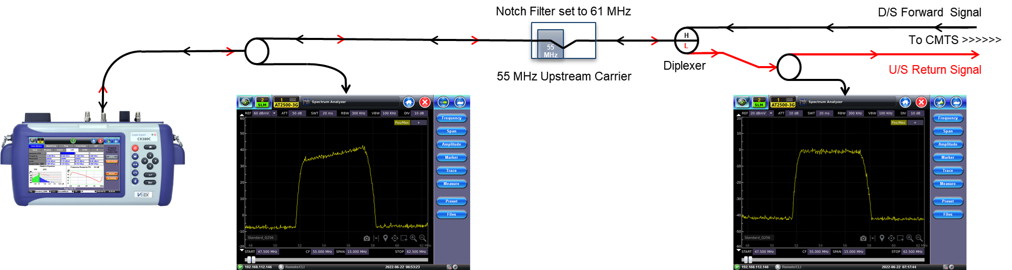
- This diagram shows a system that has the Pre-Equalization function enabled in the CMTS. (In this case, the test set is emulating the modem.)
- The same Notch filter in the return distorts one of the Upstream Carriers (SC-QAM @ 55 MHz - 6.4 MHz Bandwidth).
- When the CMTS receives the carrier that is impaired by the notch filter, the CMTS will communicate to the Cable Modem to pre-equalize the transmitted output to compensate for the impairment. Once the carrier passes through the notch filter, the pre-equalized carrier is now flat and no longer distorted. The CMTS receives the carrier in good condition and does not need any adjustments.