
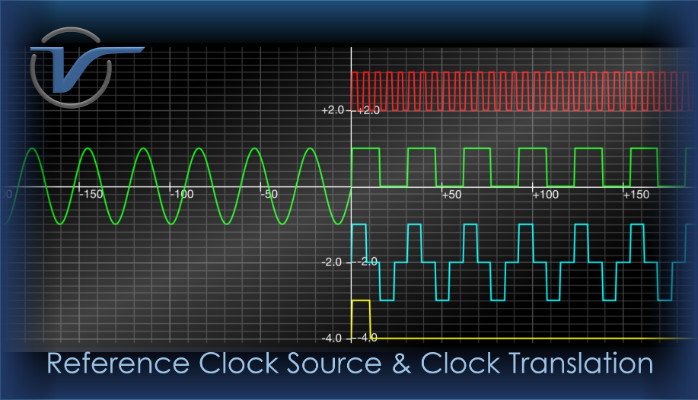
Introduction
In certain occasions we have a need for a clock reference signal different to the ones available on site, or there is no reference at all. To help in such situations we have created a guide on how to turn a test set into an impromptu precision clock source. Although VeEX test sets were not designed with this particular application in mind, we can certainly make use of their flexibility and versatility.
Note: The SyncE Test Mode is used in this application, but these setups do not require any SyncE interface or Ethernet connection. It is only used to take advantage of the Clock Translation function in the SyncE Master mode, to synthetize the required output, based on the internal precision oscillator.
1. Using the Test Set as a Clock Source (PRC or PRTC)
1.1 Requirements
A VeEX TX340s, TX320s, RXT-3400 or RXT-6200+ with:
- 1G and/or 10G SyncE licenses
- Built-in Atomic Clock option (Typ. ±0.05 ppb at shipment)
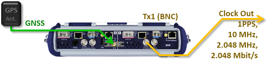
- Built-in GNSS Receiver option and antenna (optional, to act as a PRTC)
If only a T1 or E1 (BITS or SETS) clock needs to be generated, this can be easily achieved by just launching and configuring the regular T1 or E1 application and selecting the Atomic_10MHz as the TX Clock Source. The signal can be made available out of the BNC, Bantam or RJ48 ports.
Note: The internal clock could also be used as TX Clock Source (if the test set is not fitted with the Atomic Clock option). However, the expected frequency accuracy would be around ±1 to 2.5 ppm.
1.2 Setup
- Turn the test set ON and wait for the Getting Started screen. (If using the built-in atomic clock in free-running mode -frequency source only- with no GPS disciplining, please go to step 9.)
- Go to >Utilities >Settings >More >High Precision Clock >GPS, turn GPS = ON and let it Lock to satellites.
- Go to the Atomic Clock tab and set Disciplining Source = GNSS 1PPS, to enable disciplining.
- Select a Disciplining Profile according to the application (e.g., Quick or Fair for short tests or Best for long-term applications.)
- Select a Disciplining Threshold according to the antenna installation and satellite reception quality available (e.g., 20 to 50 ns for a professional roof installation or around 100ns for temporary portable antennas).
- Let the discipline process slowly correct the precision oscillator’s frequency and phase.
- Use the Phase Graph button to monitor the internal phase error. It would take about twice the Time Constant to stabilize into a flat horizontal line.
- The GPS Disciplining Status should show Locked when the desired accuracy and stability are reached.
- Follow the procedure shown in the next section, starting from step 3. In item 8 user must configure TX Clock Source = Atomic 10MHz to make the test set act as a PRC or Atomic 1PPS for PRTC applications.
2. Using the Test Set to Change a Clock Signal Format
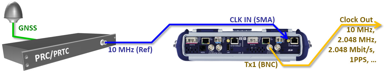
The Clock Translation function available in the SyncE Test Mode comes handy when a trusted clock signal is available, but not in the format required for the application. For example:
- You may have access to a PRTC or GPSDO with 1PPS output, but a 10 MHz or 2.048 MHz frequency reference is needed.
- You may have access to a traceable E1 SEC clock, but a 2,048 MHz or 10 MHz reference is needed.
2.1 Requirements
A TX340s, TX320s, RXT-3400, RXT-6200+ or MTTplus-340 test set with:
- 1G and/or 10G SyncE licenses
2.2 Setup
- Turn the test set ON and wait for the Getting Started screen.
- Connect the frequency reference clock signal, from the Frequency Standard, PRC or PRTC, to the test set CLK (SMA) reference input.
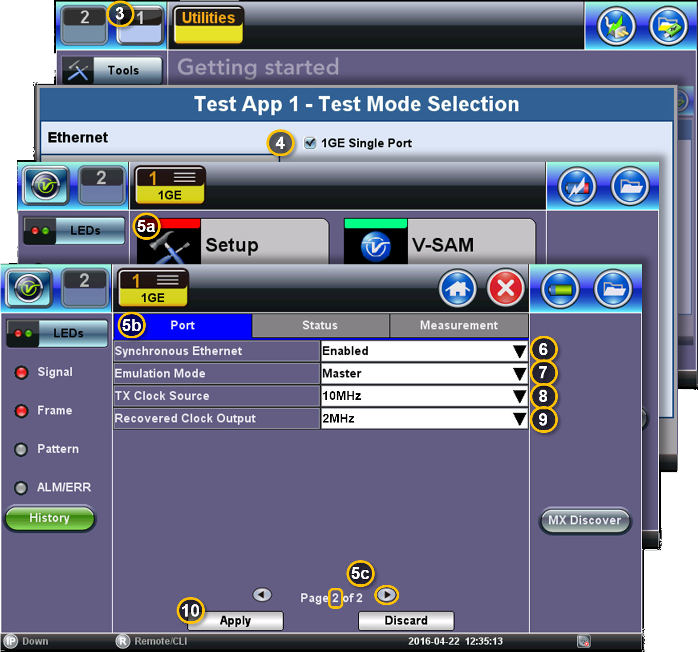
- Select Port 1 in the Test Application menu (Module 1 Port 1 or Module 2 Port 1).
- Select >Ethernet >1GE Single Port and let the test application load.
- Select >Setup >Port. Tap on the arrow icon, at the bottom of the screen, to go to Page 2.
- Set Synchronous Ethernet = Enable.
- Set Emulation Mode = Master.
- Configure TX Clock Source = 10MHz (or 2 MHz, 1,544MHz, 2.048 Mbit/s, 1PPS, etc., to match the available source).
- Configure Recovered Clock Output = 2MHz. (10 MHz, 2.048 Mbit/s, 1PPS and other options are also available.)
- Tap on the Apply button and wait until the test set finishes loading its new configuration.
- The TX1 (BNC) port now outputs a 2.048 MHz signal traceable to its 10MHz reference.
- Connect the TX1 (BNC) port from the test set to the device requiring the new clock signal.
3. Potential Limitations
Related Test Solutions
- RXT-6402 Advanced Dual 400G Multi-service Test Module
- RXT-6200 100G Universal Test Module
- RXT-3400 Advanced Multi-Service Test Module
- TX340s Advanced Multi-Service Test Set
- MTTplus-340 Multi-Service Test Module