
The RXT Test Platform is a family of modular telecommunication test and measurement equipment. It comprises of a common Test Platform (host or chassis) and different interchangeable test modules (each geared toward specific applications and/or technologies).
When it comes to user interface (GUI), feature and functions, most VeEX products are very similar, with minor differences to accommodate for the test interfaces and specific hardware capabilities. This section is generic for all products listed, with the subtle differences considered intuitive enough.
1. Getting to Know the Test Set
As part of the basic package, users may receive one of the following test platforms, test modules and accessories:
1.1 RXT-1200, RXT-1200+ or RXT-1202 Modular Test Platforms
Regardless of their individual model numbers, all the RXT-12xx chassis offer the same functionality: Provide power to the different application-specific test modules and act as the user interface to control the test system.
1.1.1 Front View
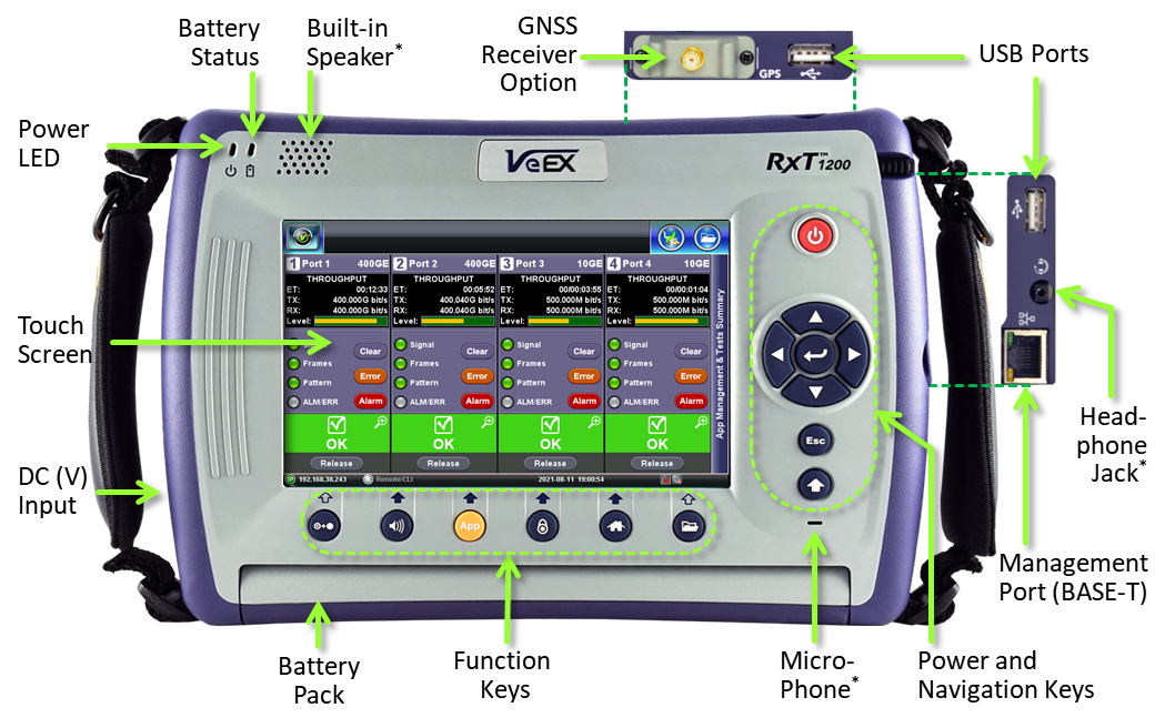
*Note: Some versions of the RXT-12xx platform may not offer microphone, speaker or headset jack (optional). However, some of the features requiring audio access may still be supported by dedicated audio jacks on the test module's connector panel.
1.1.2 Back View

1.1.3 DC Power Jacks
Depending on the test modules ordered, users receive one of the following three RXT test platform (chassis or host) models. They are very similar, with just a few differences, such as their total power handling capacity, DC port types, and a matching AC/DC adapter (non-interchangeable).
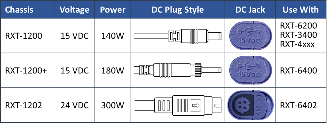
 Attention: For the RXT-1202, the flat part of the DC plug must be facing towards the front of the test set (as shown in the diagram), before plugging it in. Refer to the diagram embossed on the connector cover.
Forcing it in any other orientation would trigger its protection circuit and disable it for several minutes (in some cases could cause permanent damage). If it happens by accident, disconnect the DC plug from the test set and wait for about one hour before trying again.
1.2 RXT Test Modules
Here are some test module examples from the RXT series:
- RXT-3400 Advanced 16G Multi-Service Test Module (Uses RXT-1200 chassis)

- RXT-4100+ OTDR Module (Uses RXT-1200 chassis)

- RXT-4113+ Tunable xWDM OTDR Module (Uses RXT-1200 chassis)

- RXT-4500/4510 Series OSA Modules (Uses RXT-1200 chassis)

- RXT-6200 Universal 100G Multi-service Test Module (Uses RXT-1200 chassis)

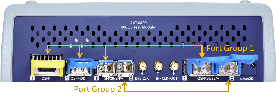
- RXT-6400 Advanced 400G Test Module (Uses RXT-1200+ chassis)

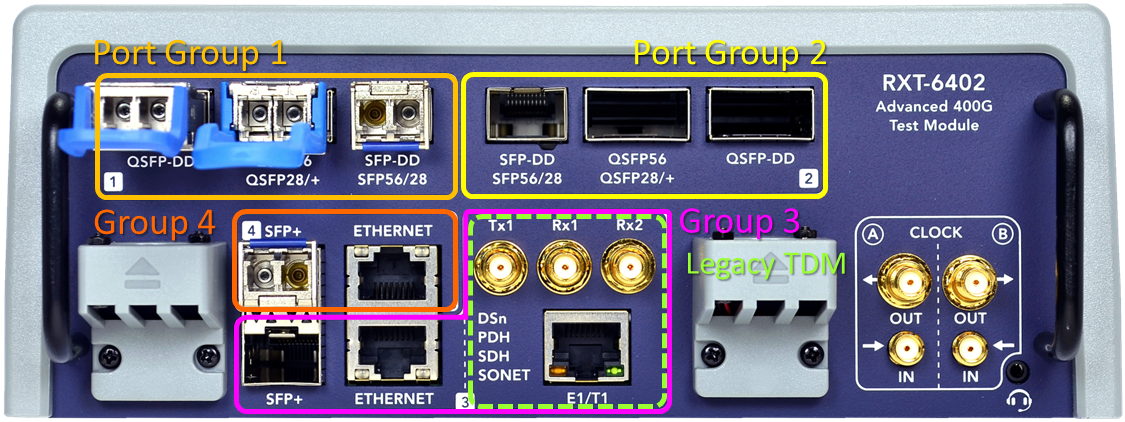
- RXT-6402 Advanced Dual 400G Multi-service Test Module (Uses RXT-1202 high-power chassis)

- RXT-6802 and RXT6802 Lite Advanced Dual 800G Test Module with QSFP-DD support (Uses RXT-1202 high-power chassis). Lite version shown.

- RXT-6811 Advanced Dual 800G Test Module with OSFP and QSFP-DD support (Uses RXT-1202 high-power chassis)

The ![]() and
and ![]() markings on the connector panel indicate the orientation of the transceivers' pull-tab, to prevent them from being inserted incorrectly.
markings on the connector panel indicate the orientation of the transceivers' pull-tab, to prevent them from being inserted incorrectly.
 Note that some SFP56 and SFP28 may come with the traditional clasp release, instead of a pull tab. These marking only refers to the orientation of the pull-tab.
1.3 Accessories & Hardware Options
- One AC/DC Adapter and Power Cord (matching the power requirements)
- Optional carrying case (if ordered)
- Optional USB WiFi 802.11a/b/g/n/ac dual-band dongle (if ordered)
- Optional USB WiFi 802.11b/g/n + Bluetooth 4.0 dongle (if ordered)
- Optional USB Bluetooth dongle (if ordered)
- Optional Optical Transceivers (if ordered from VeEX)
- Optional GNSS or Multiband GNSS receiver (comes pre-installed, if ordered)
- Optional portable GPS or Multiband GNSS antenna (if ordered)
- Optional Atomic Clock hardware option (built-in, not visible from the outside)
2. Basic Operation
2.1 Buttons

To perform an RXT-1200 platform (system) software upgrade, insert a FAT32 USB memory stick, with the installer package, into one of the test set's USB ports and press the ![]() +
+![]() +
+![]() buttons simultaneously, to start the system upgrade process.
buttons simultaneously, to start the system upgrade process.
Platform and Module software upgrades can also be performed by pointing any standard web browser to the test set's IP address and selecting Platform Upgrade and Module Upgrade from the menu.
2.2 Turning the Test Set ON and OFF
- Trun ON: Press and hold the red Power button for two seconds, until a confirmation tone is heard, and the power LED turns green (in noisy environments, refer to the power LED).
- Turn OFF: Press and hold the red Power button for about two seconds, until two confirmation tones are heard. Then the shutdown process will start.
- Forced Shut Down: In the rare case of a malfunction, our Customer Support team may instruct to press the Power button for about four seconds, until the screen turns off. Results, data or configurations are not saved.
Power Status LED
- OFF : Test set is OFF.
- GREEN : Test set is ON.
Battery Status LED
- OFF : No AC/DC power (test set is OFF or working on battery power).
- ORANGE: Battery is charging.
- GREEN : Battery is fully charged.
- Low Battery status is indicated by a periodic beeping sound, every four seconds, and displaying a warning pop-up message on the screen.
When working on battery power, once the charge capacity reaches about 10%, the test set will start beeping to notify users to plug in the AC/DC adapter. A pop-up message may also be presented on the screen. When the charge level reaches 5%, the test set automatically initiates the shutdown process, to protect the battery.
In high power consumption test scenarios, such as dual 400GE or working with coherent long-reach line-side interfaces, the test set may require the use of its AC/DC adapter at all times. If AC power is lost during such tests, the test set may shut the module off (as a safety precaution) to protect the battery from high current and overheating.
Users can tap on the battery icon, displayed on the screen, to get information about the amount of battery charge and autonomy estimate (under current usage condition).
2.3 Inserting and Removing Test Modules
No tools are required to remove and insert test modules.
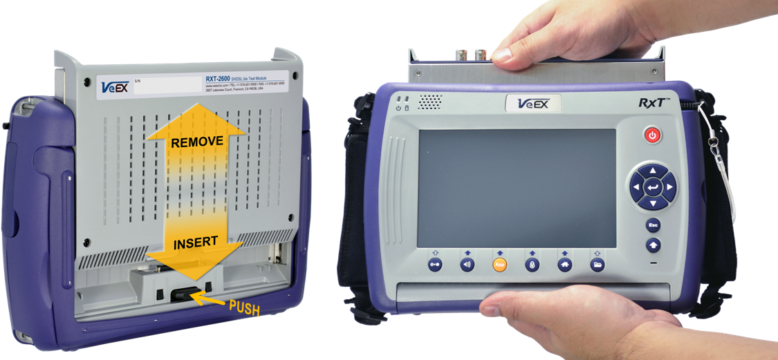
- Turn the test set OFF.
- Remove: Press the black RELEASE button on the back and pull the module out.
- Insert: Align the module with the metal guides and push it slowly until you hear the locking "click".
- If adding a new module, download the test module's software from its web page and install it using the M.Upgrade function, before using it. (Detailed installation instructions can be found in the software Release Notes)
3. Get Ready to Test
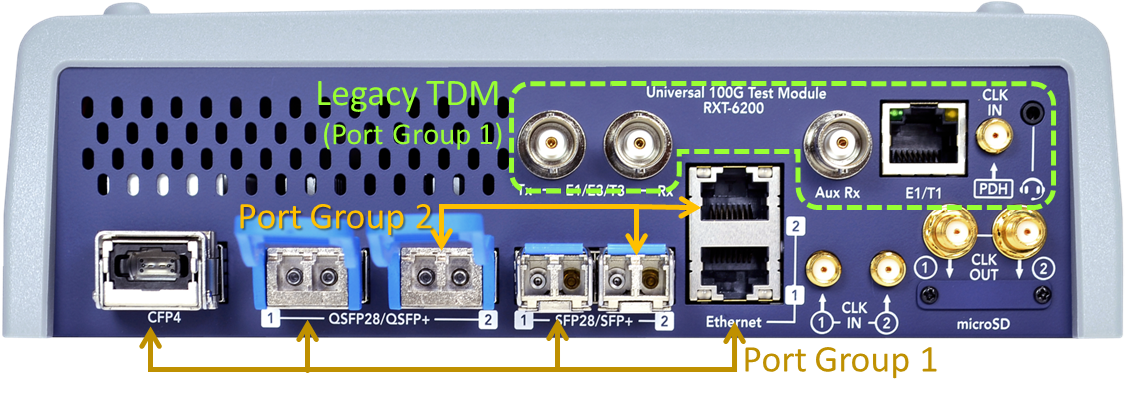
3.1 Identifying Test Ports and Port Groups
On the module's connector panel, test ports are identified by group numbers in white rounded squares. In multi-port test modules, each group can run one independent test. These groups may also be referred as P1, P2, P3, P4, etc.
Consider the test port groups as 'Test Resources' or 'Test heads'. Each one can run one test. The user interface will guide users through the available selections.
- The RXT-6200 Test Port Groups
- The RXT-6400 Test Port Groups
- The RXT-6402 Test Port Groups
3.2 Selecting the Test Port Group
- Identify the type of interface being used by the link or device to be tested
- On the test module, identify a test port group with an available port or transceiver type that matches the link or device under test. (Note: If you need to use a QSFP28 transceiver for 100GE, but Group 1 is already running a 25GE test with SFP28, even if the P1 QSFP28 slot is available, it can't be used. Then you must select a port from Group 2. Each group can only run one test.)
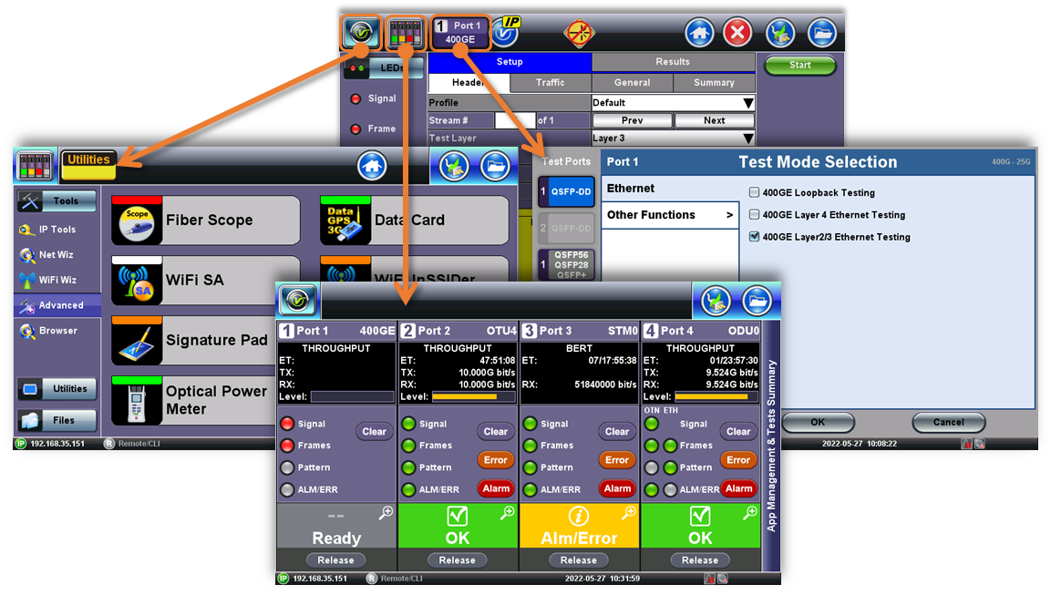
- From the GUI, select the test port group. Depending on the test module type, number of supported concurrent tests, and software version, users may have to tap on:
(A) One of the available Test Port Group buttons, 1 or 2, on the top-left corner of the screen. (If a Port Group is already being used, it will display the test type on the bottom-half of the button, with either yellow/idle, green/good or red/alarm background color indication.)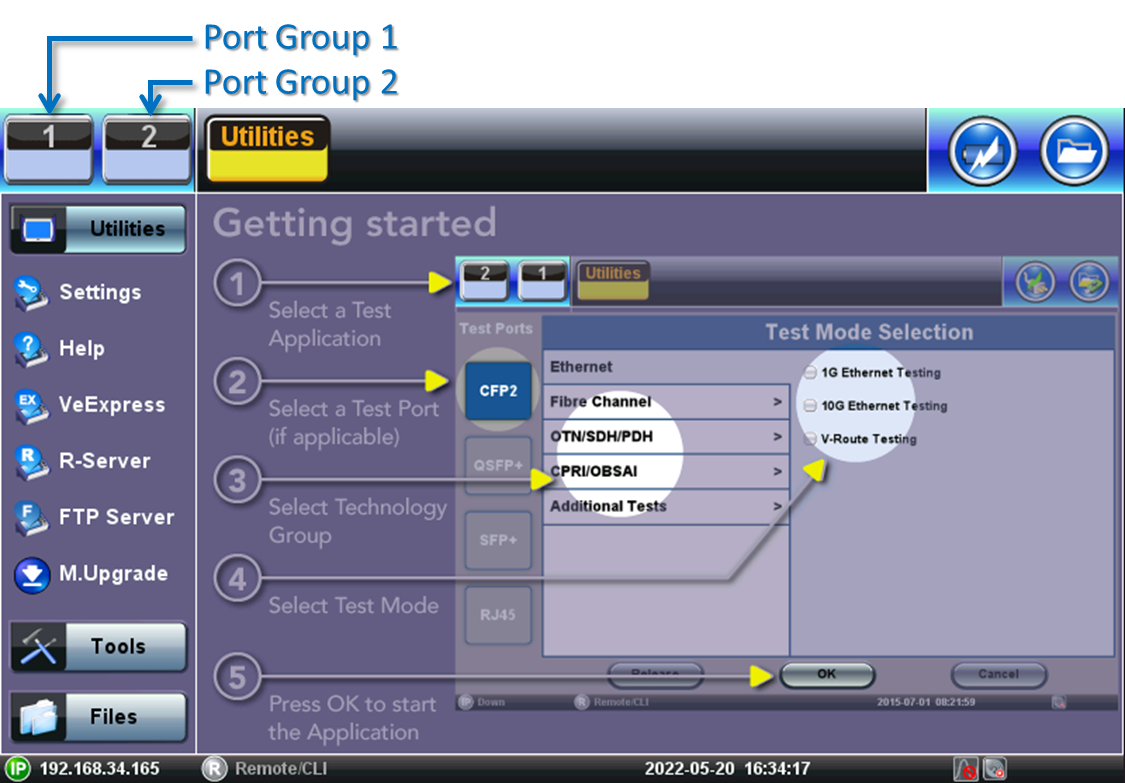
Or
(B) The New button on one of the available Test Cards, according to the test interface required for the application. Depending on each individual test module and/or hardware configuration, the screen may display two, three or four test cards. Each test card represents an independent test engine.
- The test set will display the Test Mode Selection menu, with all the test application options, protocols and/or rates available for the selected Port Group
3.3 Test Modes - Launching Test Applications

From the Test Mode Selection menu, users can select the desired:
- Test port, using the buttons on the left. (The available selection will change based on the capabilities of the selected port group.)
- Protocol (technology or link type), using the vertical tabs. (The available selection will depend on the capabilities of the selected port type.)
- Test Application, using the check boxes. (The available test functions will depend on the of the selected protocol and purchased licenses.)
- Press OK to launch the Test Application
The selected test application will start to launch (it may take several seconds).
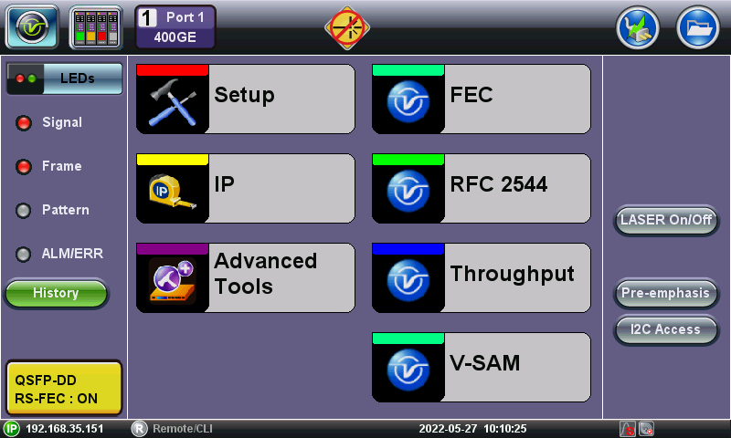
Insert the required optical transceiver (if applicable) and connect the selected test port to the Fiber, Link, Line Card and/or Device Under Test (DUT), to set up the test scenario and start testing.
Use the buttons on the left of the top bar to navigate between the different functions (System Tools/Utilities, Test Card Summary/Test Selector, Current Test/Change Test Mode)
Refer to the individual test module and test function manual for more details on the application.
3.4 Remote Access & Control
When connected to a network, the platform's management IP address (from LAN, WiFi or Cellular Modem) is displayed on the bottom-left corner of the screen. Users on the same LAN environment (or through VPN) can type the IP address on a browser's URL field, to gain remote access to the test set.
4. System Tools (Utilities)
![]() Represented by the V icon or the system Tools icon, this soft button provides access to basic and advanced configuration features related to the RXT system.
Represented by the V icon or the system Tools icon, this soft button provides access to basic and advanced configuration features related to the RXT system.
4.1 Utilities
Provides basic configuration and services related to the RXT system.
4.1.1 Settings
About (Serial numbers, software versions, licenses), Global settings, Date & Time, Screen calibration, Power/Battery status, Bluetooth pairing, screen Backlight settings, Remote Access configuration, EZ-Remote activation (allows remote users to operate the test set via Internet connection), Owner Information for the test reports, High Precision Clock Sources settings for GNSS/GPS and atomic clock options and Map Downloader to attach location to test reports.
4.1.2 Help
Open local copy of the general user's manual.
4.1.3 VeExpress™ Client
Cloud-based License and Software management offered free of charge by VeEX (requires Internet access).
- Software Management allows users to check for new software updates, download them to USB memory stick and upgrade the test platform and/or test module.
- License Management allows users to retrieve newly purchased licenses and share existing licenses (test features) with colleagues.
4.1.4 VeSion® R-Server™ Client
Centralized Workflow, Results and Asset Management System (requires corporate subscription and Internet access). If enabled, allows users to download workorder-related tests profiles, software, and upload test results directly from the test set. Among other features, R-Server administrators or managers can also monitor the inventory and track test sets in repair, etc.
4.1.5 FTP Server
This simple built-in FTP client allows users to login and connect to an FTP server, select test result files and upload them directly from the test set. Internet connection is required.
4.1.6 M. Upgrade (Module Software Upgrade)
Users can download the latest test module software from the product page at www.veexinc.com, unzip it, copy the content to the root of a FAT32 USB memory stick, insert it into one of the test set's USB ports, wait for it to be recognized, and select the Module Upgrade function to update its software.
To perform the platform (system) upgrade, follow a similar procedure after downloading the RXT-1200 software package, but instead of using the M. Upgrade function, turn the test set OFF and then press the ![]() +
+![]() +
+![]() buttons simultaneously, to start the system upgrade process.
buttons simultaneously, to start the system upgrade process.
Platform and Module software upgrades can also be performed by pointing any standard web browser to the test set's IP address and selecting Platform Upgrade and Module Upgrade from the menu.
4.2 Tools
Provides additional system configuration and troubleshooting tools for the Management Ports (LAN or WiFi used to control the test set and transfer information).
It also offers software clients for test equipment such as Fiber Inspection Scopes, Optical Power Meter, OPX-BOX OTDR (WiFi, Bluetooth, USB), OTDR viewer (to analyze SOR trace files), WiFi Spectrum Analyzer dongle (USB), and cellular modem client (USB).
4.3 Files
Provides access to Test Results, Test Profiles (saved test setups), screenshots, etc., saved in the internal storage. Users can also browse the files on any attached USB memory stick.
5. Information & Resources
RXT Family Page: https://www.veexinc.com/products/rxt1200
Related Test Solutions
- RXT-3400 - Advanced Multi-Service Test Module
- RXT-4100+ - OTDR Series Modules
- RXT-4113+ - xWDM Tunable OTDR Series Modules
- RXT-4500 & RXT-4510 - Optical Spectrum Analyzer (OSA) Modules
- RXT-6000e - 100G Universal Multi-Service Test Module
- RXT-6200+ - Advanced 100G Universal Multi-Service Test Module
- RXT-6400 - 400G Multi-Service Test Module
- RXT-6402 - Advanced 2x400G Multi-service Test Module
- RXT-6802 - Advanced 2x800G Multi-service Test Module