
Introduction
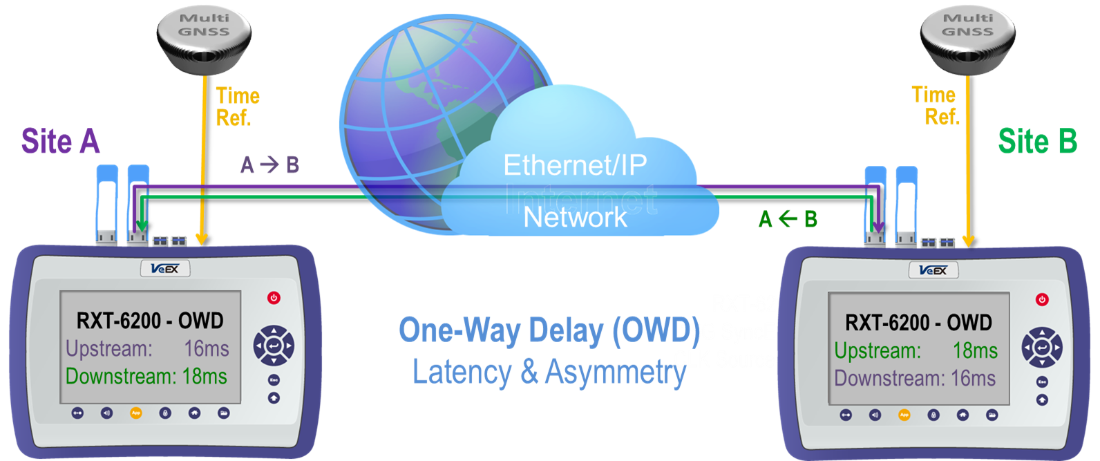
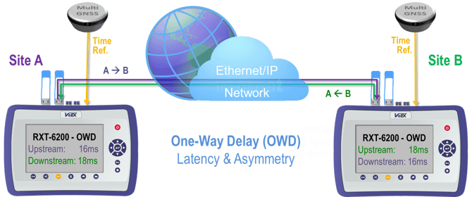
One-Way Delay (OWD) is different than the common Round-Trip Delay/Time (RTD or RTT) measurement. The latter uses a simple loopback device at the far end to return all test packets so the main test set can measure the time each test packet takes to complete the full A→B→A trip. Assuming that the network latency is the same in both directions (symmetric) one can divide the total delay by 2 to get an estimate of the link latency. However, that may not be true for all links or network architectures, which may be asymmetric in nature. Then end-to-end OWD is used to provide a direct and more accurate measurements of the latency in each direction. However, there is an added complexity to the workflow, since it requires two test sets and accurate local time references (1PPS).
Certain time-sensitive applications need symmetric data links (or knowing their specific asymmetry), requiring dual-ended One-Way Delay (OWD) tests to qualify or verify the network latency in each direction of the link. Two synchronized test sets (with the same timing or common accurate clock), one at each end of the link under test, are needed to measure the latency for each timestamped test packet. Two geographically dispersed test sets can be synchronized using a Primary Reference Time Clock (PRTC) or Global Navigation Satellite System (GNSS) receiver. The rising edge of a standard 1PPS signal indicates the beginning of a second everywhere in the world, so it is used as a reference to keep the two test sets in sync (same time).
Network elements (switches and routers) and long fiber optic cables are usually responsible for most of the latency added to the path (link). Fiber cables are responsible for adding a constant delay around 0.5μs for every 100m (328 ft) of cable. Switches and routers, on the other hand, can add variable delays due to electronics, queuing/buffering and prioritization. The resulting total delay (or latency) results is a somewhat constant value with a small Packet Delay Variation (PDV) component. Hence, it is important to measure the Maximum, Minimum and Average delay values.
1. LOCAL Measurement Method (Lab)

1.1 Requirements
- One dual-port test set.
- One-Way Delay License.
- Access to both ends of the link under test.
In Dual Port mode, the test set allows running a bi-directional OWD test with only one meter. This is useful for troubleshooting problems in a lab or repair center or fine-tuning network settings when access to both ends of the links are available at one site.
1.2 Configuring the Test Set
1.2.1 For 100GE and 50GE Test Modes
- Select
 Port 1 >
 QSFP28/+ >Ethernet >100G/50G Ethernet Testing, then press OK
  .
. - Go to the >Setup >Measurement tab, set ToD Synchronization Source = LOCAL to enable the OWD measurement, using a common internal clock reference.
- Tap on the
 Home or
  Exit buttons to go back to the main menu and launch the Throughput test application.
 - Select the Setup / General tabs, tap on the
 Page button to go to Page 2 of 3, and verify that Delay Measurement Mode = Local 1-Way.
1.2.2 For 25GE, 10GE, 1GE and Below
- Select Port 1 >
 SFP28/+ >Ethernet >25G/10G/1G Ethernet Testing, then press OK .
 - Go to the >Setup >Measurement tab, set ToD Synchronization Source = LOCAL to enable the OWD measurement, using a common internal clock reference.
- Tap on the Home or Exit buttons to go back to the main menu and launch the Throughput test application.
- Select the Setup / General tabs, tap on the Page button to go to Page 2 of 2, and verify that Delay Measurement Mode = Local One-Way Delay.
1.3 Measuring Local OWD
Once both test ports are synchronized to the internal clock, connect them to the ports on the device or link under test.
- For Port 1, turn the Laser ON
 .
. - Press Start.
- Use the Throughput test's LEDs and Results to verify proper end-to-end connectivity (Signal, Frame, Pattern and no errors or alarms).
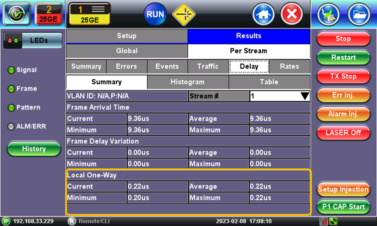
- Select the Results / Per Stream / Delay tabs.
- Repeat the same steps for Port 2.
Use the test application buttons 1 and 2 to toggle between the two active tests and see the One-Way Delay results for each direction.
2. Point-to-Point Method (Field)
2.1 Requirements (for both sites)
- One test set at each location.
- One-Way Delay Licenses.
- Reference Time Clocks (e.g., GNSS/GPS or 1PPS clock signal).
OWD is a coordinated test that requires both test sets (and users) to be ready. Users must follow each other’s status over the phone, or any other communication mean. If using the built-in GNSS option, users in sites A and B must have the GNSS Receiver hardware installed in the test set and have its antenna installed with unobstructed wide view to the sky and connected with a known cable delay (or at least exact cable length and specifications).
 When using the built-in GNSS receiver, connect the antenna to its SMA connector, go to >Utilities >Settings >More >High Precision Clock Source >GNSS, turn GNSS receiver ON, wait until satellites are detected (at least four with >36 dB-Hz) and the GNSS Status = Lock (the GPS icon
 ![]() on the bottom-right corner of the screen turns green and the Status screen displays coordinates). This is not required if an External 1PPS clock is used as reference.
on the bottom-right corner of the screen turns green and the Status screen displays coordinates). This is not required if an External 1PPS clock is used as reference.
For more details refer to How to Configure the Precision Timing GNSS (GPS) Receiver or type GNSS on this page's Search field.
2.2 Synchronizing the Test Set
2.2.1 For 100GE and 50GE Test Modes
- Select Port 1 or 2 >
 QSFP28 >Ethernet >100G/50G Ethernet Testing, then press OK .
 - Go to the >Setup >Measurement tab, set ToD Synchronization Source = GPS 1PPS to enable the OWD measurement, tap on the Sync button and confirm that the status changes to Locked.
- Tap on the Home or Exit buttons to go back to the main menu and launch the Throughput test application.
- Select the >Setup >General tabs, tap on the Page button to go to Page 2 of 3, and verify that Delay Measurement Mode = One Way Delay with GPS. (If it only shows Round Trip Delay - RTD, it may have lost sync. Go back to step 2 and press Sync again.)
Notify your far-end partner that you are ready and confirm that both have followed the same steps and are ready to start.
2.2.2 For 25GE, 10GE, 1GE and Below
- Select Port 1 or 2 >SFP28/+ >Ethernet >25G/10G/1G Ethernet Testing, then press OK .
- Go to the >Setup >Measurement tab, set ToD Synchronization Source = GPS 1PPS to enable the OWD measurement (some test sets, equipped with the optional built-in Atomic Clock, may also offer the Atomic 1PPS selection).
- Tap on the Home or Exit buttons to go back to the main menu and launch the Throughput test application.
- Select the >Setup >General tabs, tap on the Page button to go to Page 2 of 2, and verify that Delay Measurement Mode = 1-Way Delay with GPS/CDMA.
The test can also be performed using one of the 10/100/1000BASE-T RJ45 test ports.
Notify your far-end partner that you are ready and confirm that both have followed the same steps and are ready to start.
If the synchronization source is a local Primary Reference Time Clock (PRTC) providing a physical 1PPS timing signal, use a short coaxial cable to connect this signal to the CLK A or CLK B SMA input, for Port Group 1 and Port Group 2 respectively.
2.3 Measuring Point-to-Point OWD
Once both test sets are synchronized to the standard second (1PPS), connect their test ports to the respective local Ethernet port belonging to the link under test.
- Turn the Laser ON .
- Press Start.
- Use the Throughput test's LEDs and Results to verify proper end-to-end connectivity (Signal, Frame, Pattern and no errors or alarms).
- Select the >Results >Per Stream >Delay tabs.
On the bottom of the screen, each test set will display the OWD (Latency) values for the incoming test packets.

3. Expected OWD Results
Although the measurement display resolution could go down to around 20 ns, this type of measurements is not meant for measuring delays induced by short cables. Due to the time error uncertainty of GNSS/GPS receivers, the results for just short cables may not be correct.
Typical applications, such as measuring actual links, or even the small delays between two ports of a switch, should return latency values in the milliseconds range.
Related Test Solutions
Multi-service and Ethernet test sets with GNSS/GPS Receiver hardware (option) and OWD testing capabilities:
-
RXT-6802 - Advanced Dual 800G Multi-Service Test Module (QSFP-DD)
-
RXT-6811 - Advanced Dual 800G Multi-Service Test Module (OSFP, QSFP-DD)
-
RXT-6402 - Advanced Dual 400G Multi-service Test Module (QSFP-DD)
-
RXT-6200 - 100G Universal Test Module (QSFP28)
-
RXT-3400 - Advanced Multi-Service Test Module (SFP+)
-
MTX642 - Dual 400G Portable Test Set
-
MTX640 - Dual 100G/400G Portable Test Set
-
TX300s-100G- Multi-service Testing Up to 100G
-
TX340s - Advanced Multi-Service Test Set
-
MTTplus-340 - Multi-Service Test Module