
Sometimes, on evaluation labs or the field you may have the need to generate physical clock signals that are in sync with each other, like 1PPS and 10MHz. If you have a Quad TX340s (TX300s platform loaded with two TX340sm modules) or an RXT-6200+, with the SyncE and/or IEEE1588 PTP licenses, you may refer to the following procedure to use the test set as impromptu signal generator. A Quad TX340s or RXT-6200+ can generate up to two clock outputs simultaneously (Dual TX340s, RXT-3400, MTTplus-340 or MTTplus-320 can only generate one clock signal). The signals can be tied to GNSS 1PPS, GNSS+Atomic_Clock, external reference or the internal quartz oscillator, depending on the quality desired.
- If the internal (optional) GNSS/GPS is to be used as the reference, go to >System Tools >Utilities >Settings >More >GPS/High-Precision Clock >GNSS Receiver to configure it and turn it on. Once it has locked, you can follow the steps below.
- If the internal (optional) Atomic Clock is to be used as a reference, once the GNSS survey has locked its position, go to the >Atomic Clock tab and set the Disciplining Source = GNSS 1PPS. Once the atomic clock's 1PPS Disciplining Status is Locked, follow the steps below.
- Select Port Group 1 (P1), SFP+ interface, 10G Ethernet Testing mode to launch the application.
- Go to Setup, page 2, enable SyncE, and set Emulation Mode as Master
- Set the TX Clock Source to Atomic_1PPS (best), GNSS/GPS_1PPS (good), or Internal (ok), depending on the application requirements. If absolute timing alignment is not required, we recommend using Atomic_10MHz.
- Set the Recovered Clock Output to 1PPS, 10MHz or any of the other clock frequencies available. This signal will be available in the CLK OUT (SMA connector) A or 1.
- Press Apply. (There is no need to connect it to an ethernet port or start a test)
- Select Port Group 2 (P2) and repeat the steps above, selecting the other clock signal to come out of CLK OUT (SMA) B or 2
- If the TX340s has two modules installed (four ports), you may repeat the same steps for the other two ports, to output up to four different clock signals.
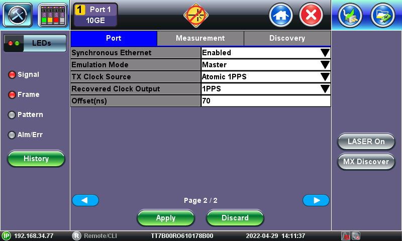
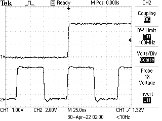
Note: The timing signals from the two ports may have different delays, so they may come out of phase. With the help of an oscilloscope, use the 1PPS Offset (ns) setting (e.g., 70ns) to align them, if necessary. This is also used to remove any timing delays induced by the test set and cable delay compensation.
Related Test Solutions
- RXT-6402 Advanced Dual 400G Multi-service Test Module
- RXT-6200 100G Universal Test Module
- RXT-3400 Advanced Multi-Service Test Module
- TX300s-100G Multi-service Testing Up to 100G
- TX340s Advanced Multi-Service Test Set
- MTTplus-340 Multi-Service Test Module