
 If you are a visual learner, you may benefit from the quick guide videos available at the end of this article (Section 5).

The test platform offers highly accurate and stable clock reference options to provide precise frequency, timing (1PPS) and time-of-day (ToD) to its test modules and applications. These internal physical clock references can be used for frequency, phase, time error (TE) and wander measurements. Accurate UTC time of day from GNSS (Global Navigation Satellite Systems) can be used for time sensitive tests such as PTP timestamping, Time Error and one-way-delay measurements.
VeEX's products offer two types of precision timing oriented GNSS Receivers:
- Precision-timing Multi-constellation GNSS Receiver (P/N: Z88-00-009P), supporting up to two constellations at a time, including GPS (L1C/A), GLONASS (L1OF), Galileo (E1B/C) and BeiDou (B1I)
- High-precision Multi-band Quad-constellation GNSS Receiver (P/N: Z88-00-010P), supporting up to four simultaneous constellations and two bands, including GPS (L1C/A, L2C), GLONASS (L1OF, L2OF), Galileo (E1B/C, E5b) and BeiDou (B1I, B2I)
They offer optimized accuracy and stability with location survey and precision timing mode, providing locked 3D position mode to improve timing stability for stationary applications. These are the recommended modules for atomic clock disciplining (PRTC), wander, phase error, time error, holdover, delay measurements, as well as location and timestamp tagging applications.
1. Basic Configuration
To access the GNSS settings and status feature, tap on the ![]() or
or ![]() System Tools button (icon) and go to >Utilities >Settings >More >GPS/High Precision Clocks (the menu structure may differ slightly from product to product).
System Tools button (icon) and go to >Utilities >Settings >More >GPS/High Precision Clocks (the menu structure may differ slightly from product to product).
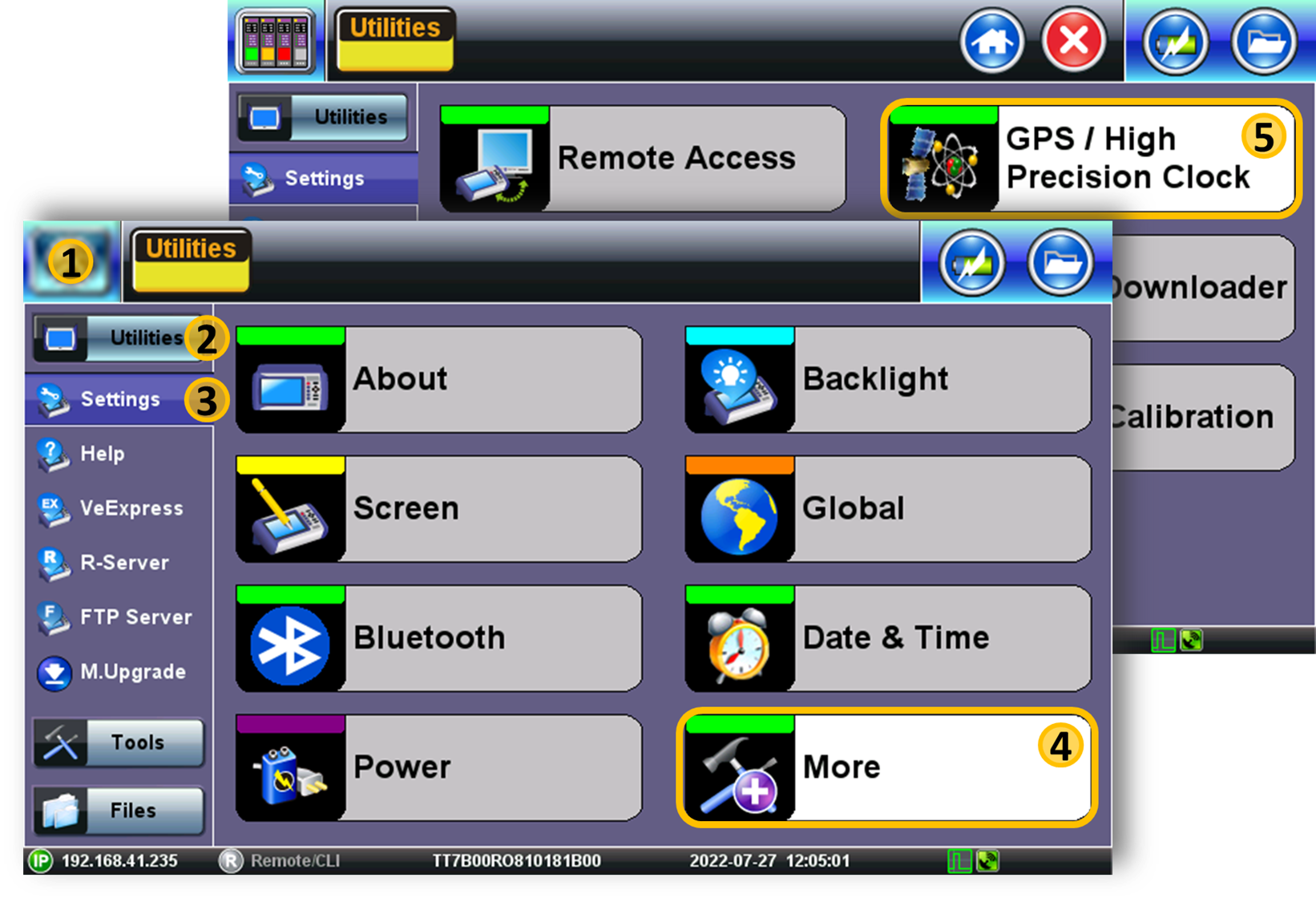
Select the GNSS Receiver tab to access the Settings menu.
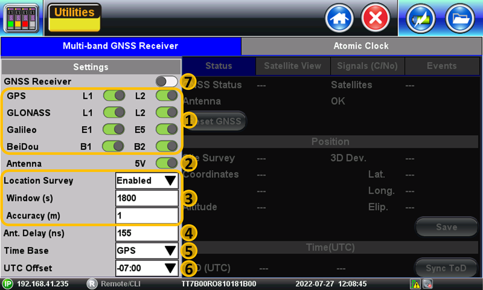
- Constellations & Bands - Select the desired satellite systems (constellations) and frequency bands, as supported by the antenna and receiver being used.
- Antenna Power - Activate or deactivate the 5V antenna power source. When turned ON, the test set powers the active antenna. Turn it OFF is the antenna is being powered by a separate source.
- Location Survey Profile - Accurate timing recovery requires accurate coordinates (Latitude, Longitude, Altitude). The process of determining the most accurate antenna position is called Survey. During the survey process, the receiver monitors the 3D position variations until its values are within a circular area defined by the Accuracy (m) parameter and stay within that range for the specified Window (s) of time. Once such criteria are met, the receiver locks the coordinates and focuses on calculating time only. Having accurate fixed position reduces the variations (wander) in the reference clock output (raw 1PPS timing signal).
- Location Survey - Disabled (Not recommended for precision timing applications), Enabled (Recommended for timing applications. It uses multiple measurements to automatically calculate the most accurate position possible), Manual (User can manually enter accurate coordinates on record or retrieve previously saved coordinates for the location of the antenna).
- Window - Minimum time required for a stable position, before declaring lock and switch to time-only mode. Value in seconds (1800s or 3600s recommended for the most accurate results).
- Accuracy - Minimum required position variance, within the time window, required to declare lock and switch to time-only mode. Value in meters (1m recommended for the most accurate results).
- Antenna Delay - Enter the total antenna cable delay, from the antenna to the GNSS receiver port. Any error in the total cable delay entry will turn into phase error at the 1PPS output. Value entered in nanoseconds.
- Time Base - User can select the base for time-of-day calculations: UTC, GPS, Galileo, GLONASS, or BeiDou systems.
- UTC Offset - Time zone offset used for local time of day (ToD) calculations.
- GNSS/GPS - Turns the GNSS receiver ON and OFF.
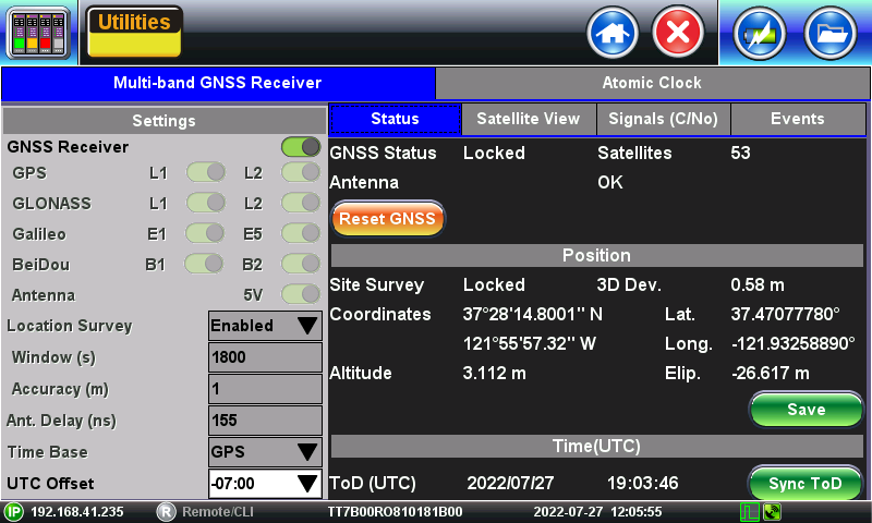
Once the GNSS Receiver is activated, it will take a couple of minutes for the initial lock to GNSS satellites (GNSS Lock) and acquire initial location and time of day. Then the survey process begins, and the 3D Deviation should start to become smaller and converge to the lowest possible attainable value (depending on antenna type, installation and conditions). Once the Window+Accuracy criteria is met, the Site Survey will be Locked. The process can take several minutes. The total time would depend on how stringent the settings are, antenna type, signal quality and environmental conditions at the test site, among other factors.
The signal quality (C/No density) is very important to achieve the desired accuracy. It is recommended to have at least four satellite signals at or above 40 dB-Hz.
If the target position accuracy can't be achieved, consider repositioning the antenna for better sky visibility and/or less interference (recommended). If that is not possible, then increase the Accuracy threshold to a value that can be achieved (<4m), however, this is not recommended.
![]() Connect the coaxial antenna feed cable to the GNSS RF input port (SMA, 50Ω). Although hard SMA adapters for BNC, TNC and N antenna cable connectors are commercially available and seem convenient, it is highly recommended to use short adapter cables instead, in order to relieve any mechanical stress from the otherwise thick and rigid RF coaxial cables.
Connect the coaxial antenna feed cable to the GNSS RF input port (SMA, 50Ω). Although hard SMA adapters for BNC, TNC and N antenna cable connectors are commercially available and seem convenient, it is highly recommended to use short adapter cables instead, in order to relieve any mechanical stress from the otherwise thick and rigid RF coaxial cables.
2. GNSS Status & Monitoring
2.1 GNSS Status Indicator Icon
Located on the right side of the bottom bar, this always-visible indicator provides basic information about the health of the GNSS receiver.

2.2 GNSS Summary Status
2.3 Satellite (Sky) View

This visual color-coded polar view of the GNSS satellites in view (overhead) can help in identifying blind spots and antenna placement issues.
2.4 Signal Quality (C/No Density)
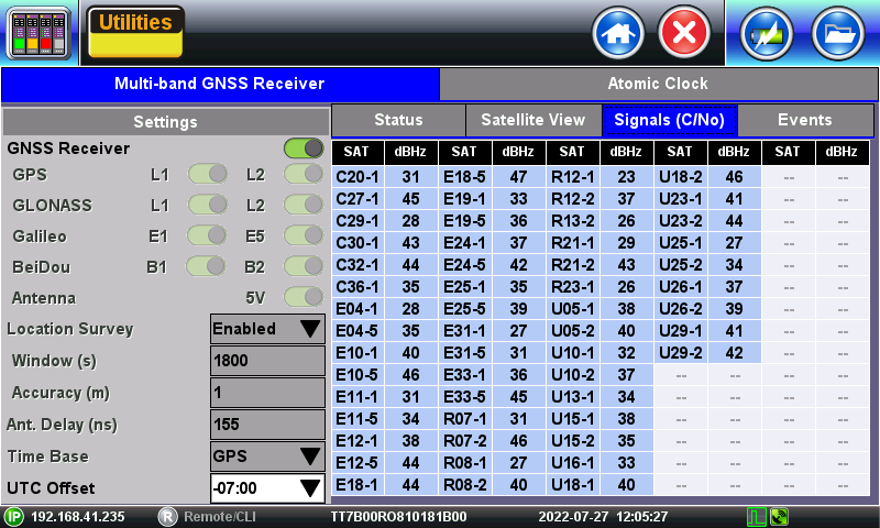
Displays the Carrier-to-Noise density (signal quality) for all the bands and satellites in view being tracked. It is recommended to have multiple satellites with >39 dB-Hz.
Satellite Vehicle Number (SVN) nomenclature: X##-B
- X - Operator: U (USA's GPS), R (Russia's GLONASS), E (Europe's Galileo), C (China's BeiDou)
- ## - Satellite number
- B - Frequency bands
- 1: L1C/A, L1OF, E1B/C, or B1I
- 2: L2C, L2OF, or B2I
- 5: E5b
2.5 Events Log

Logs any significant GNSS and antenna related issues that have occurred while the receiver is being active.
3. GNSS 1PPS Output
Once properly synchronized, the GNSS receiver provides an accurate One-Pulse-Per-Second (1PPS) timing signal, with the rising edge aligned to the beginning of the standard second, to the test platform. This internal physical signal is not directly available to the user. Applications that require the use of this precision timing signal provide GPS_1PPS or GNSS_1PPS selections in their user interfaces (GUI), to be used as a Reference Clock, Transmit Clock or Measurement Clock.
This internal GNSS 1PPS signal can also be used to discipline (correct) the internal Atomic Clock (if available), to produce more accurate and stable frequency and timing clock references.
4. Related Test Solutions
5. Related Materials (Videos)
Introduction to VeEX's Timing GNSS Receivers
GNSS Receiver Configuration Guide
Atomic Clock Disciplining Theory & Configuration (Video)