
Let's start by clarifying that, by definition (ITU-T X.21 standard), X.21 is a Synchronous interface. It uses its S (bit) and B (byte) synchronization signals (pins) to identify the data it carries. Technically, there is no Asynchronous X.21.
However (and unfortunately), some network equipment vendors and/or users take the liberty of creating their own names, nicknames or panel labels for some of the interfaces in their products (sometimes to adapt to the way some of their main customers call it). In some cases, it may be because the signals or connectors have been modified one way or another (no longer standard).
The standard X.21 synchronous datacom interface is quite simple. So, if the S and B synchronization signals are removed from the interface, then perhaps the transmitted stream of data may need to resemble an asynchronous bit stream similar to the one carried by the popular RS232A interface (with start, data size, stop bit, and parity check bit), but transmitted over a balanced V.11 physical data signal.
If the above is true, MTX150 users may be able to use the RS422A Full Duplex (FD) datacom mode to test it, since it is also a V.11 physical data signal with an asynchronous data structure. Perhaps this is what could have caused the confusion, since RS422A uses V.11 signals and V.11 is often associated with X.21, that may have transformed into the "X.21 Asynchronous" idea.
What datacom test cable to try:
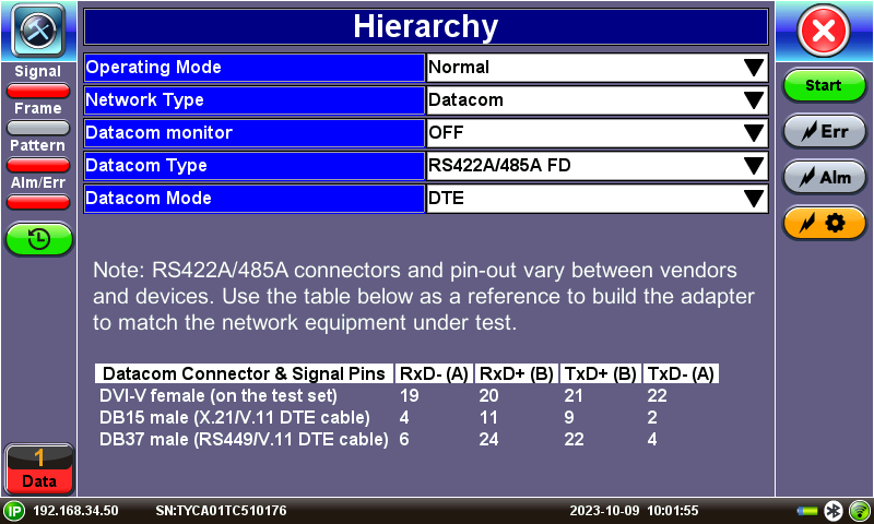
- The MTX150 RS422A/485A FD datacom mode uses the X.21/V.11 DB15 DTE test cable (P/N F02-00-019G). So, if the so called "X.21 Async" borrowed the name because of the DB15 connector, then this should work.
However, if a different connector or pin-out are required, making an adapter cable should be easy, since only four wires (two pairs) should be required. Users have two options to build such test cable:
- Create a custom adapter cable, directly from a DVI (male) to the desired DTE connector, based on the female DVI datacom connector pin-out from the MTX150. Make sure the A/- and B/+ signal pairs are on the same twisted pair.
- Use the X.25 DTE DB15 test cable supplied with the MTX150 test set, along with a modular adapter to wire the desired DTE connector, based on the pin assignments shows on the test set screen.


Technically, this information could be applied to other asynchronous interfaces that are based on V.11 signals.
Related Test Solutions
- MTX150 - Multi-service Installation & Maintenance Test Set.