OTDRs and the Evolving Optical Distribution Network
The choice of OTDR type matters, as it depends on the type of fiber links, networks being tested, and test conditions. The use of fiber optics within communication networks has been evolving at an increasingly faster pace! Originally used for point-to-point (P2P) Core, Transport, and Metro applications, now point-to-multipoint fiber networks are being used to reach individual subscribers at the edge.
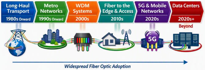
Figure 1. Fiber Optics Adoption Timeline
As PON technology continues to evolve, so do the architectures of Optical Distribution Networks (ODNs), wavelengths used and the coexistence with previous versions and other services.
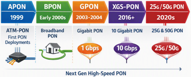
Figure 2. Evolution of PON Technology
There are three main types of PON ODN deployment architectures, each one posing their individual set of challenges, which a true PON-optimized OTDR must accommodate:
-
Centralized Split – Uses a single splitter between OLT and Subscribers' ONTs. It started with a 1x16 split ratio; however, the use of 1x32 and 1x64 is now common in areas with high population density, such as apartment and office buildings (i.e., multi-dwelling units or MDUs).
-
Distributed Split (Cascaded) – Uses two or three balanced splitters, in series, to provide services over a wider geographical area, such as suburban neighborhoods, venues, and campuses. Although it may not be the most efficient signal distribution scheme, it may be considered one of the most efficient deployment of fibers, typically serving up to 128 homes, and perhaps 256 in the near future.
-
Distributed Taps (Asymmetric Split) – Uses Through-Taps to drop signals to individual subscribers along the way. The Taps are made of two splitters: one asymmetric 1x2 splitter with one of its drops to pass-through the network traffic and the other spliced to a balanced splitter (2 to 16 drops) to connect services to a specific subscriber area. At the end of the PON link, a Terminated-Tap (single balanced splitter) is used.
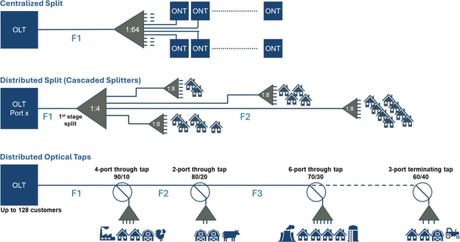
Figure 3. Common PON Network Topologies
Not All OTDRs are Created Equal
OTDRs, the most versatile characterization, verification and troubleshooting instrument for fiber optics, have also evolved to meet the specific testing challenges of diverse Optical Distribution Network (ODN) architectures. Today’s OTDR offerings can be classified into different categories, such as the traditional P2P OTDRs, PON OTDRs, (tunable) xWDM OTDRs, RFTS systems for proactive monitoring, as well as OTDRs for dark fiber (construction and maintenance), OTDRs for live fiber testing (in-band and out-of-band), among others. Each with their own set of specialized characteristics and strengths, fine-tuned for their specific applications.
-
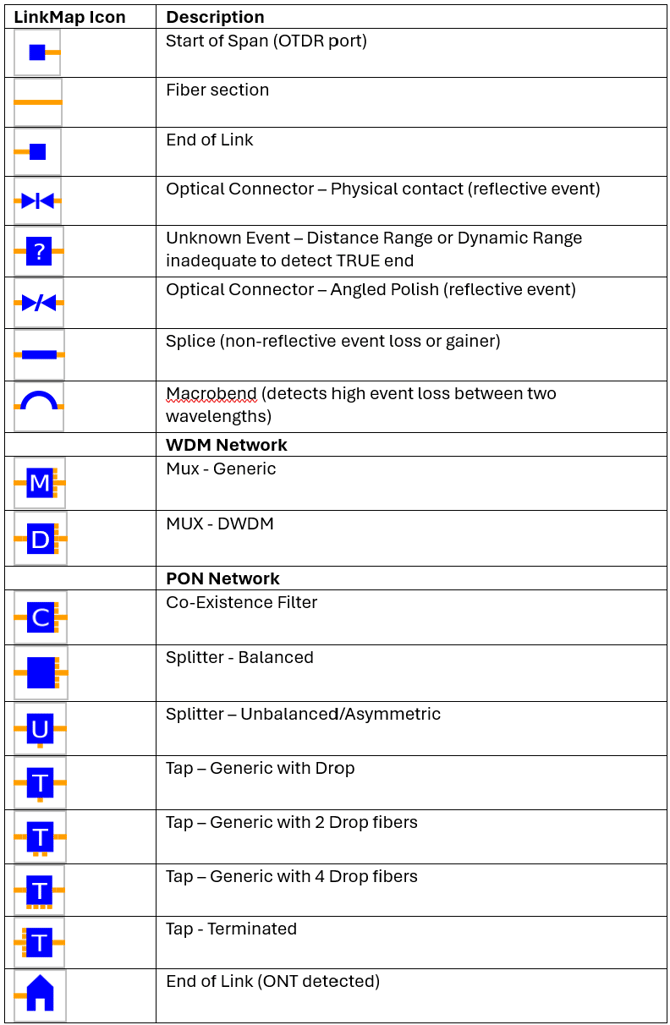
Historically, P2P OTDR measurements primarily identified a simpler set of events, such as fusion splices, mechanical splices, APC and UPC connectors, macrobends, breaks and end of fiber.
-
In Wavelength Division Multiplexing (WDM) networks, the links between passive MUX/DeMUX elements are similar to P2P fiber links. However, multiplexer insertion loss typically ranges from approximately 3 to 10 dB to keep receiver (Rx) levels within the acceptable operating range. xWDM OTDRs require tunable lasers (Tx) in order to test the routes assigned to the wavelength or channel under test.
-
PON networks introduce passive splitters and Taps, which produce significantly higher event losses and are required to be identified properly. Because PON is a shared medium, OTDRs used for activation and troubleshooting must support live, out-of-band testing (typically at 1625 nm, 1650 nm, or another non-PON wavelength) to avoid disrupting other active subscribers on that branch.
PON networks pose unique measurement challenges to traditional P2P OTDRs and, if used for PON ODN testing, their results may lead to failure, misleading interpretation of events or misunderstandings.
Core Technical Differences
| Traditional P2P OTDR | PON-Oriented OTDR | |
| Network Architecture | Point-to-Point (Single dedicated path). | Point-to-Multipoint (Shared path, branched via splitters). |
| Wavelength Options | 1310/1550 nm for dark fiber; Optional 1625 nm or 1650 nm for live fiber. | 1310/1550 nm for dark fiber; Filtered 1625 nm or 1650 nm for live fiber. Filtered 1350 nm may also be used for non-intrusive macrobend detection. |
| Internal Optical Filter | None (can be 'blinded' by live traffic). | Built-in bandpass/cut filter to block active subscriber traffic. |
|
Test Site Connection |
At either end of the Link under test. |
From the Customer end of the Link (recommended) |
| Splitter Recovery | Unoptimized; treats splitters as catastrophic fiber breaks. | Optimized recovery from high-attenuation events (up to 1x64 or 1x128 splitters). |
| Trace Analysis Mode | Single Pulse Width. Optional Multi Pulse. | Multi-Pulse Width recommended. |
Why Multi-Pulse Testing?
- Short pulses map the closely spaced events before the splitter. (e.g., connectors, splices.)
- Medium pulses measure the splitter loss itself.
- Long pulses blast through the splitter(s) to measure the feeder fiber between the OLT and splitter(s).
- The software then combines all the events detected into a single, comprehensive iconic link map representation, events table and OTDR trace.
Testing PON ODNs with PON OTDRs
A PON ODN has Optical Line Terminators (OLTs) located at a central office or cabinet, optional coexistence (CEx) filters, feeder fibers connecting to distributed passive splitters, and drop fibers connecting the final (edge) splitter or Tap to the subscribers' ONTs.
-
To test a PON branch or drop, the OTDR is normally connected close to the subscriber side of the ODN (at the ONT, NID, or last splitter) and used to test through the splitters or Taps back toward the OLT.
-
Service activation technicians typically need to test only the drop fiber between the subscriber and the last splitter.
-
During fiber construction, crews may test from the OLT side toward the network edge, provided that no drop fibers have been installed. Once drop fibers are in place, reflections from multiple branches can complicate the measurement.
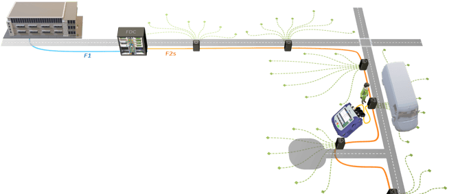
Figure 4. PON Network Testing from Subscribers' Side
One characteristic of modern PON OTDRs is their high dynamic range, which is required due to the large splitter losses, along with the ability to properly identify PON components in the events table and the simplified link map. VeEX’s PON-optimized OTDRs address different test scenarios by offering four extra PON test modes, to be used depending on the job requirements:
-
PON/B – For Balanced PON ODNs with one to three cascaded splitters, with the effective testing length limited by ODN loss budget. These OTDR tests are often performed upstream, towards the OLT.
-
PON/U – For Unbalanced PON ODNs with asymmetric Taps and 2 to 16 drops per Tap, ending with a terminating Balanced Tap. The number of Taps and length are limited by ODN loss budget. These OTDR tests are often performed upstream, towards the OLT.
-
ONT to Splitter – Primarily a Drop fiber test mode for validating and troubleshooting, with the OTDR connected at the subscriber’s side, towards the network. The OTDR will confirm the presence of the Splitter and whether bad couplings, bad splices, breaks or macro bend exist in the drop fiber.
-
Splitter to ONT – Local test for construction verification, prequalification before activation, and troubleshooting of Drop fibers (≤ 2 km), with the OTDR connected after the last Splitter and testing towards the subscriber. The OTDR will also attempt to confirm if there is an ONT already connected at the subscriber’s site.
The total Optical Power Loss (OPL) budget is limited by the PON Class (based on Tx Power and Rx Sensitivity). A common misconception is to rely solely on the published dynamic range value of a standard OTDR (e.g., 40 dB), to assume it can test any PON ODN (based on the table below). However, we must keep in mind that the standard OTDR dynamic range calculation is based on a 20 µsec Pulse width (2 km event resolution), large datapoint spacing (≥ 8 m) and Test time = 3 minutes. That would not work for the shorter lengths of PON networks and its relatively close events.
The table below summarizes the Physical Media Dependent (PMD) layers’ minimum and maximum OPL, associated with the different ODN Classes.
|
Physical media dependent (PMD) layer specifications: XGS-PON (G.9807.1 02/2023) |
|||||||
|
|
Optional λ set (incl. GPON bands) |
Basic Wavelength set |
|||||
|
ODN class |
B+ |
C |
GPON C+ |
10G/25G/50G N1 |
10G/25G/50G N2 |
E1 |
E2 |
|
Min Loss |
13 dB |
15 dB |
17 dB |
14 dB |
16 dB |
18 dB |
20 dB |
|
Max Loss |
28 dB |
30 dB |
32 dB |
29 dB |
31 dB |
33 dB |
35 dB |
To effectively test from ONT to OLT, and detect all splitters/Taps, a PON OTDR not only requires sufficient dynamic range, but may also need to use a multi-pulse testing approach. Starting with a short pulse width to find every event before the splitter(s) and wider pulses after high loss splitters, to be able to identify subsequent events. However, the wider the test pulses are, the larger the event dead zone (DZ) becomes, hindering the OTDR’s ability to identify adjacent events as the split ratio and loss increase. For this reason, the largest pulse width typically used for PON testing is 500 ns (50 m event resolution).
The maximum reach of a PON ODN (from the ONT to the OLT) is determined by the cumulative splitter loss and the optical power required at the receiver, as defined by the OPL budget. Use the fiber-loss specification in dB/km at 1270 nm or 1310 nm to calculate the maximum allowable fiber length.
|
PON/B OTDR Splitter Detection Limitations by Pulse Width |
||||||||
|
PON/B |
P1: 30 ns (~3 m) |
P2: 120 ns (~12 m) |
P3: 180 ns (~18 m) |
|||||
|
|
PON DZ m |
Loss dB |
PON DZ m |
Loss dB |
Meas. Rng dB |
PON DZ m |
Loss dB |
Meas. Rng dB |
|
1x2 |
< 8 |
3.75 |
16 |
3.84 |
23 |
No 3rd Pulse Width |
||
|
1x4 |
< 8 |
7.67 |
16 |
7.68 |
23 |
|||
|
1x8 |
< 8 |
10.43 |
16 |
10.21 |
22 |
|||
|
1x16 |
< 20 |
13 |
< 20 |
13 |
23 |
|||
|
1x32 |
< 40 |
16.53 |
< 40 |
16.5 |
22 |
|||
|
1x64 |
n/a |
n/a |
< 60 |
19.77 |
23 |
< 60 |
19.7 |
30 |
- PON/B ODN length can be up to 20 km, depending on the total splitter(s) and fiber loss. The higher the splitter losses (split ratio), the shorter the total ODN length or reach.
- PON/U Tap ODN length can > 20 km, up to 40 or 60 km. When testing towards the OLT, the PON OTDR sees the loss of a single splitter (up to 1x16) plus all subsequent Tap(s) thru-losses back to OLT (the other drop splitters are not part of the optical path under test).
To properly identify closely spaced splitters or taps, the OTDR must be able to use the shortest pulses possible, while still being able to reach the end of the path. This is why features like VeEX's V-Scout Multi Pulse OTDR Testing are critical for PON testing.
Standard OTDRs with adequate dynamic range (e.g., ~40 dB), could still be used to perform tests on Centralized Split ODNs with single 1x16 balanced splitter (~13 to 15.3 dB loss) or even on some Distributed Tap networks. That is assuming that the initial Tap loss doesn’t exceed ~16 dB, that the test pulses used are not too wide and end users know how to setup the thresholds and interpret the large splitter losses correctly (not confuse them with macrobends or "fiber cracks"). For distributed Tap networks, the initial Tap loss will depend on the asymmetric split ratio and the total number of drops. (Example: 97/3 tap dropped to two homes ~ 21.5 dB loss).
Conclusion / Takeaway
-
Traditional point-to-point (P2P) OTDRs and PON-oriented OTDRs differ fundamentally in how they handle high optical loss, split network paths, and active data traffic.
-
PON-optimized OTDRs are also well suited to P2P testing. However, traditional, older, or lower-dynamic-range P2P OTDRs may struggle in certain PON environments, particularly those with multiple splitters or large number of drops. Selecting the right OTDR for the application is therefore essential.
-
Older P2P OTDRs, even if they are in perfect working conditions and meet the high dynamic range requirements, may not be able to properly handle PON-related thresholds or identify high-loss events correctly, such as splitters, because they were not defined in their post analysis algorithms.
-
PON-optimized OTDRs are essential to accurately test the physical layer of modern PON ODN architectures, with their high splitter losses and complex topologies, while standard OTDRs are limited to testing simpler, and perhaps longer, link configurations with lower loss budgets.
-
As fiber-optic network construction, installation, activation, and troubleshooting continue to expand, many technicians are entering the field with limited or no prior fiber-optics experience. Providing a clear understanding of the available tools helps them select the right instrument for each job, minimize measurement errors, and avoid costly repeat truck rolls.
For Further Reference
Below is an example of the expanded event icon list from VeEX's OTDRs, describing some the passive ODN elements that can be identified by modern OTDRs. A traditional (older) P2P OTDR may only be able to identify the first eight event types, while a PON OTDR can identify most of them.