Some people may say "just place the antenna on a window facing south". But, why south? Perhaps such statements may come from aligning TV dish antennas, on the northern hemisphere, towards geostationary satellites. But that does not apply to GNSS constellations.
The ideal GNSS installation is facing UP and with a wide unobstructed view to the sky, such as on a roof. However, it is understood that this is not always possible, especially for temporary test applications. Sometimes users need to find ways to get enough satellite reception, with a portable antenna, limited cable length and/or partial view to the sky. In many cases, it is trial an error until one can find at least four satellites with signal quality (C/No density) greater than 33 dB-Hz.
The GNSS receiver status tab in the test set must display location coordinates, before it can calculate local time and output the 1PPS reference clock signal required for most precision timing applications. If the test set can't resolve the coordinates, the antenna must be relocated to a "better" place.
The Site Survey must achieve the Lock status, in order to provide the most accurate and stable timing possible. If the coordinates on the Status screen are still changing, the output timing would have a wander component as a result.
Things To Avoid
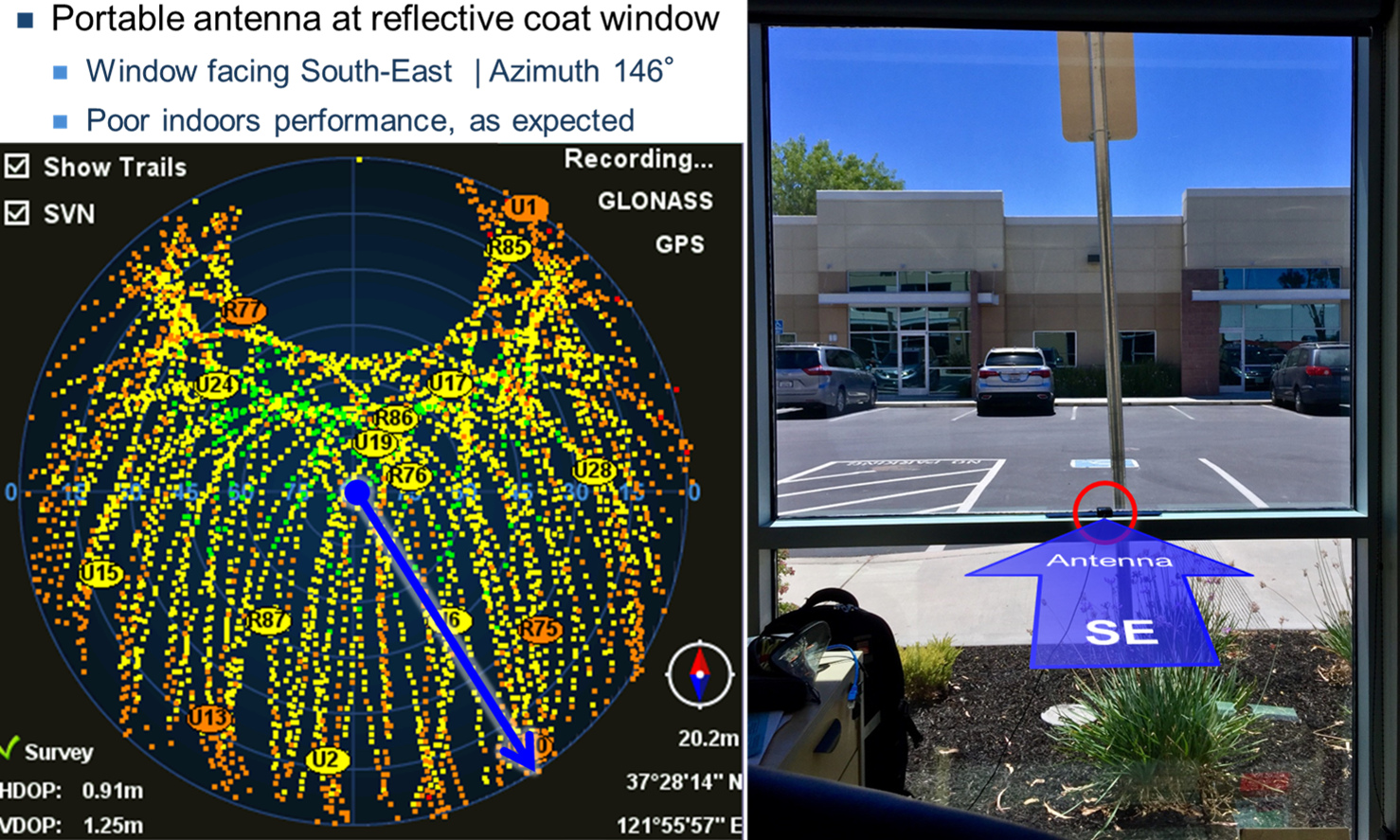
- It is important to keep in mind that some modern high-efficiency windows have thin metal coatings that block (or attenuate) RF signals.
- Even if the building, where testing is being performed, doesn't have reflective metal coatings, the building(s) around may have, and that could create an environment with multi-path (reflected RF signals), which could also affect RF signal quality.
- Placing the portable patch antenna vertically (its top side facing horizontally)
- Using these precarious antenna placements for high precision or long-term measurements (e.g., test requiring accuracies in the nanoseconds range or very stable reference). Measurements, like One-Way Delay (OWD) may be OK, since the results would be in the microsecond or millisecond range.
Few Things That Could Help
- Using multi-constellation GNSS receivers and antennas. In partial sky view, the more satellites available, the better. A receiver supporting GPS and GLONASS has less satellites to work with than one supporting GPS, GLONASS, Galileo and BeiDou.
- Using multi-band GNSS receivers and antennas. A dual band receiver has access up to twice as many satellite signals, increasing the odds of signals with decent signal quality. Also, the different frequency bands offer different penetration properties for different materials.
- Using high-quality, high gain, high sensitivity multi-band multi-constellation antennas. For example, LNA gain >37 dB, noise figure <1.9 dB.
- Adjust the location survey thresholds, to match the environment, so the GNSS can lock its position and turn into precision timing mode. The specific numbers would be different for different situations. Users could monitor the GNSS 3D Deviation for a few hours to see what is the lowest number they can get, and then set the Accuracy(m) threshold to a slightly higher number, so the survey can successfully lock. Users may also have to adjust the evaluation Window. It is important that the Survey locks, so the time (although not the most accurate) is at least stable.
In any case, be mindful of all the compromises being made and set the right (quality) expectations, as some of those less-than-ideal antenna installation conditions may have an effect in measurements accuracy and stability.
As a reference, below is the signal coverage of the same GPS+GLONASS antenna, mounted on the roof, with a wide and clear view to the sky. Green is GOOD, Yellow signals attenuated by nearby trees, Orange and Black are signals blocked by the horizon's skyline (mountains and buildings around).

Good To Know
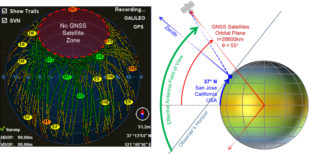
The antenna's GNSS coverage is not only ruled by its position or how good (open) its sky view is. For example, the graph below, on the left, shows all the satellite vehicles tracked by one antenna, over time. It clearly shows a "dead zone" that satellites' orbits don't cross, due to their orbital planes. The positions of these zones depend on the antenna location's latitude. Antennas in the southern hemisphere will show the no satellite zone on the bottom (south) of the graph. Note that the zone highlighted in red doesn't necessarily mean No Signal, it means No Satellites.
The other hard limit for the antenna's satellite view is the horizon. So, no matter how much one tilts the antenna towards the south (or north) it won't be able to "see" satellites past its geographical horizon.