

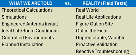
Does it work? In many cases, yes—the GNSS receiver may synchronize. The most important question, however, is how accurate and stable that indoor synchronization really is?
Numerous standards, publications, and guidelines address how to verify and certify (test) the accuracy and stability of high-precision Primary Reference Time Clocks (PRTCs), including high‑class GNSS‑disciplined atomic clocks and PTP grandmaster clocks. However, field tests requiring time synchronization at remote locations present significant challenges. In many cases, the link or device under test (for example, an NTP or T‑SC PTP client) is the only timing source available on site, so an external timing reference must be brought in.
Timing synchronization needs extend well beyond PRTC and PTP Time Error measurements. They also apply to other link‑related tests, such as latency, One‑Way Delay (OWD) and asymmetry, all of which are directly affected when no reliable local timing reference is available. As a result, users in the field often have to devise creative ways to obtain a somewhat accurate and stable clock reference in less-than-ideal conditions.
This article is intended to highlight the risks realted to indoor GNSS use, point out what to avoid, and offer practical suggestions for reducing the impact of known factors.
The Motivations for Indoors GNSS Use
Despite the well-known limitations and repeated explanations provided to users about why it is not recommended, requests for guidance on how to configure and operate GNSS/GPS receivers indoors continue to arise for timing-oriented communications test and measurement applications in the field, where no other clock reference options are available. This persistence is further reinforced when some vendors present indoor GNSS operation as a key feature and a perfectly viable solution without providing further details or the caveats.
From the end user’s perspective, many test locations simply do not provide a suitable 1PPS timing reference or access to well-documented roof-mounted GNSS antennas. However, field technicians still have to find ways to test, validate, verify, diagnose, and troubleshoot certain timing-oriented links, services and hardware installations.
To obtain temporary timing synchronization for test equipment, during verification work, users frequently resort to convenient shortcuts, or try to cut some corners, especially while working under their tight time constraints. However, the associated tradeoffs and limitations are often overlooked.
We do recognize the strong need to establish timing references in locations where none exist. In many situations, it is not practical or even feasible to install a temporary roof antenna, deploy long coaxial extensions, or even have access to the exterior of the building. Often, the only available option is that portable GNSS patch antenna, with approximately 5 m (16 ft) of cable, that came with the instrument. However, if/when shortcuts are taken in the name of practicality, it is essential to understand the potential consequences, the resulting quality degradation, and the measures required to minimize, compensate, and account for some of the negative effects. However, we shall not refer to those test and measurement tasks as "certifications" or "verifications". They should be considered more of a "timing check" or perhaps "timing validation".
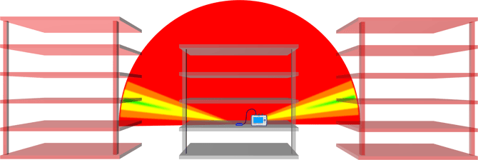
Sometimes you may also encounter counterproductive advice that could further degrade the conditions, when given without context, such as the popular “place the GNSS antenna next to a south‑facing window.” This could become especially problematic because modern high‑efficiency windows use metallic reflective coatings that can also block RF signals. We have even seen portable patch antennas taped vertically to a window—so the patch only “sees” roughly half of the horizon—instead of being mounted horizontally and pointed toward the zenith, as intended, to provide full 360° × 180° coverage.

The SkyView™ GNSS satellite signal quality heat map examples below (polar reception quality patterns), for two indoor antenna locations, are both predictably poor. However, the antenna placed near the metal-coated window exhibits more orange and yellow, and less green C/No signatures towards the south‑east hemisphere than the antenna positioned farther away from the reflective window.

Note that antenna 1, located far from the window, shows some green patches of fair reception quality directly above (near the zenith), which should provide better geometric dilution of precision (PDOP) and improve timing accuracy, when compared to antenna 2, next to the window. However, the results will be different for every site or building type.
We do recognize that, in many cases, there are no other options and the objective is not on having a nanosecond‑level, high‑precision timing reference—as required for certifying PRTCs or critical synchronous communication infrastructure—but for some practical transmission latency measurements used for validation, such as network or link One‑Way Delay (OWD) and asymmetry, for which the total results are typically expressed in microseconds or even milliseconds.
The Challenges of Using GNSS Antennas Indoors
Using GNSS antennas indoors for precision timing references during testing, validation, or troubleshooting introduces substantial risks, primarily due to severe signal attenuation and multipath interference. These conditions impair time transfer performance and undermine the one pulse-per-second (1PPS) accuracy required when testing critical infrastructure.
Major problems include:
-
Line-of-Sight Requirements: GNSS systems require a direct (unobstructed) line of sight to the sky, (theoretically) with at least four good satellites to triangulate a precise position. Indoor environments, with their numerous obstacles and lack of open sky view, hinder this requirement.

-
Severe Signal Attenuation: Building materials (concrete, rebars, steel beams, metal roofs, metalized glass, etc.) weaken or block the already faint GNSS signals by 15 to 40 dB. They further degrade the carrier-to-noise density (C/No) and can cause intermittent connection dropouts.
-
Low-elevation satellites: Roof and upper floors obstruct a large portion of the satellites available directly overhead. That leaves low-elevation signals, which travel through significantly more atmosphere, making them highly susceptible to attenuation, interference and distortion. Also, there are more landscape obstacles and impairments at lower elevation angles, such as buildings, trees, mountains, multi-path (refractions, reflections), RF noise, jamming exposure, etc. Be aware that some GNSS receivers may have default elevation masks set between 5° and 15° to ignore low-horizon satellites, reducing the number of available satellites even more.
-
Poor Satellite Geometry (High PDOP): The obstruction of large portion of the satellites available directly overhead, leave the receiver to calculate position using only the sub-optimal arrangement of low-horizon satellites it can "see". Poor geometric position dilution of precision (PDOP) directly degrades location and timing accuracy. Antenna altitude error has a significant impact on 1PPS time error (TE).
-
Multipath Errors: Signals reflecting off walls, windows, ceilings, and internal structures before reaching the antenna can cause erroneous time-delay calculations. Because the reflected signals travel longer paths, the receiver's clock may be driven with unaccounted time lag. Also, signals coming in at a shallow, low-elevation angles are much more likely to bounce off of obstacles before reaching the antenna (e.g., buildings, metal roofs, trees, water, or the ground).
-
Indoor RF Interference: The already faint satellite signals, further attenuated by the obstructed sky, have to compete against powerful electromagnetic noise generated by indoor electrical equipment, lighting systems, Wi-Fi routers, Bluetooth devices (among others), causing localized Radio Frequency Interference (RFI) that can interfere with the already weak GNSS signals.
-
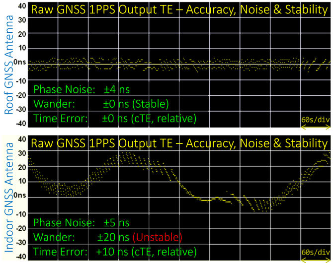
Unstable 1PPS Timing Reference: Poor signal quality (C/No) and high PDOP can cause the receiver’s calculated coordinates to vary continuously, preventing the Location Survey from locking its position. As a result, the GNSS receiver’s timing output becomes unstable because the path delay calculations keep changing. This can cause the 1PPS to wander over time, with relative time error variation reaching or exceeding ±100 ns. Since the 1PPS serves as the timing reference for time-based measurements, the test results will also keep changing. In end-to-end applications such as One-Way Delay, the time error from both GNSS references is additive (e.g., ±200 ns) and such inaccuracy and variability will be reflected on the results.
-
Receiver Holdover Limitations: When indoor signal loss causes the GNSS receiver to lose lock entirely, an optional precision atomic clock (if available) can enter into holdover mode, to maintain timing continuity. These local clocks will drift over time, degrading sub-microsecond precision if the signal is not reacquired. Also, the limited time allocated for field test and measurement activities may not allow for proper (disciplining of an atomic clock or OCXO.
A Few Suggestions to Improve Your Odds
When/if a typical job and site conditions require the use of portable GNSS antennas indoors for millisecond- or microsecond-level delay measurements under constrained signal reception, the following suggestions could help you achieve the best level of synchronization possible, to perform the work with reasonable accuracy (uncertainty) and stability expectations.
1. Select the Best GNSS Receiver Option Available
Ensure the instrument (or external 1PPS reference) is equipped with a high‑precision, timing‑oriented GNSS receiver that supports multiple bands and multiple constellations. Ideally, it should track all four major systems (GPS, GLONASS, Galileo, and BeiDou) simultaneously, with at least two frequency bands per constellation. In general, having access to more satellites within the partial sky view, and receiving more signals, improves timing performance and robustness.
Recommended VeEX GNSS receiver option: P/N Z99-99-034P - Multi-band GNSS Receiver for High Precision timing applications. Supports concurrent GPS (L1C/A, L2C), Galileo (E1B/C, E5B), GLONASS (L1OF, L2OF), and BeiDou/BDS (B1I, B2I) bands. This is a field upgradeable hardware option for TX300s, MTTplus and RXT-1200 test platforms. A software license may also be required.
2. Select a Good Portable GNSS Antenna
Select a high-gain multi-band multi-constellation active antenna, supporting all the satellite systems and frequency bands covered by the GNSS receiver. The more satellite signals supported, the better. However, if a well-documented coax GNSS antenna feed is available on site, from a roof or exterior antenna, then use it (an accurate cable feed delay value is required).
Recommended VeEX active portable antenna: P/N Z99-99-033G - Multi-band GNSS Portable Antenna. Supports GPS L1/L2, GLONASS G1/G2, Galileo E1/E5, BeiDou/BDS B1/B2 (1.2 and 1.6 GHz) bands. High 38 dB LNA gain, Magnetic mount, 5 VDC, 5 m coax cable with SMA connector (26 ns typical cable delay).
3. Indoor Antenna Placement
Place the GNSS antenna facing up and keep it away from reflective (metal coated) windows, metal cabinets, racks, etc. Indoors signal quality (C/No) is going to be poor anyway, however you should use your instrument's C/No table and graphs to identify the best possible indoor placement. Ideally you should strive to find at least four high-elevation satellites (≥30°) with signal quality (C/No) ≥36 dB-Hz.
-
In the United States, buildings constructed primarily with wood and gypsum board tend to allow slightly better GNSS signal penetration. Nevertheless, large or high‑rise structures still present significant challenges for reliable satellite reception.
-
In areas with brick, cinder block, concrete, rebar, steel and metal roofing constructions, the GNSS signals get significantly attenuated or blocked, and may render indoor GNSS-based synchronization useless.
-
Secure sites, like data centers, are also very challenging in terms of GNSS signal reception quality, as well as the things you are allowed to bring in or do inside.
Having a long, flexible, good quality, thin coaxial extension at hand may be helpful in certain scenarios. For portable applications, we recommend a ≤30 m (100 ft) extension cable made of low-loss 50 Ohm LMR-195 cable (similar to RG-58 and RG-142). This can help position the antenna outside, close to non-coated windows, or be placed at a location with better signal reception quality.
4. Identify and Account for All Known Variables and Error Sources
Reduce and compensate for any known, controllable time error sources to improve overall timing accuracy. For example, use a timing‑oriented TDR (such as the VeEX CX41 TDR) to directly measure the exact delay of the coaxial antenna cable and extensions (avoid doing manual conversions or estimates). Then enter the total value in the GNSS Cable Delay Compensation setting. If a TDR is not available, you could estimate the delay by carefully measuring the cable length (if possible) and confirm its velocity of propagation (VP%) from its datasheet, however that would only give you a close approximation. Clearly label each portable antenna and any coaxial extension cables with their corresponding (measured) delay values.
VeEX's portable multi-band GNSS antenna, with 5 m (16.4 ft) cable, has a typical cable delay of 26 ns.
5. Try Adding a Ground Plane
The aperture of a GNSS patch antenna refers to its effective electromagnetic area used to collect signal energy from the sky. Because the physical dimensions of patch antennas are much smaller (e.g., 2 x 2 cm), relative to the ~20 cm GNSS wavelength, the aperture and corresponding gain are heavily dependent on the physical footprint of its underlying ground plane.
The patch antenna's aperture efficiency directly improves as the ground plane gets bigger. A 10 x 10 cm circular or square metal ground plane, with the antenna placed on its center, is recommended if your specific antenna supports both upper and lower GNSS bands (such as L1, L2 and/or L5), which require a wider radial surface for optimal front-to-back ratio. Check the antenna documentation for their official ground plane recommendations. Keep in mind that by attaching magnetic mount antennas on top of metal cabinets, their irregular ground plane will have an effect on their performance.
6. Do Not Ignore the Site Survey Process - Let it Lock!
Use the GNSS Site Survey function properly and let it finish, to obtain the most accurate coordinates (antenna's position) and allow the GNSS receiver to reach a stable survey lock. This may require running the survey for several minutes, or up to an hour, to determine the best attainable 3D Deviation at that specific indoor location and then setting the Survey Threshold accordingly (for example, using 20 m to 40 m, instead of the typical 1 to 3 m threshold you may set for outdoor or roof antenna configurations).
The objective is for the survey to lock the position (GNSS receiver stops updating its coordinates) to limit timing calculation variations caused by position drift. If the GNSS receiver continues to adjust its position due to poor signal quality, the derived timing will also wander. However inaccurate, a locked position provides a more stable 1PPS reference. Once the GNSS receiver gets the most accurate position possible, and locks it, it becomes more resilient because it could get timing from even a single good satellite.
![]() Should you be worried about a 20 to 40 m position uncertainly? It depends! Given that the objective is 1PPS timing accuracy rather than precise positioning, and that GNSS satellites in Medium Earth Orbit (MEO) are approximately 20,200,000 m away, the corresponding timing error contribution from a 20 to 40 m 2D position deviation is expected to be relatively small.
Should you be worried about a 20 to 40 m position uncertainly? It depends! Given that the objective is 1PPS timing accuracy rather than precise positioning, and that GNSS satellites in Medium Earth Orbit (MEO) are approximately 20,200,000 m away, the corresponding timing error contribution from a 20 to 40 m 2D position deviation is expected to be relatively small.
For an oversimplified illustration, consider a satellite directly overhead (at zenith) and a perfectly flat terrain. With a 2D position error of about 20 to 40 m, the corresponding variation in the RF path length is only about 0.01 to 0.04 mm, which translates into small fractions of a nanosecond of timing error. However, the worst-case scenario is if the entire 3D position error is along the vertical axis (altitude), then the resulting uncertainty in signal delay could reach approximately 66 to 133 ns for the same range of distance error (at 3.33 ns/m propagation delay).
For those communication link delay measurement applications, under the described constraints, it is very important to set achievable location survey thresholds, in order to get a locked (constant) position (coordinates), for a more stable 1PPS clock output.
7. You May Need to Rely on Averages
If signal quality (C/No) is poor and PDOP is high, the raw GNSS 1PPS timing reference output may become unstable, exhibiting excessive wander that affects the accuracy, stability, and repeatability of the test results. Under those conditions, it may be necessary to rely more heavily on averaged results, since the instantaneous measurements may fluctuate too much during runtime. Averaging may help stabilize and improve the consistency of the measurements; however, it does not improve timing accuracy.
8. Take Advantage of Disciplined Precision Oscillators
If available, make use of the instrument's Atomic Clock option to help stabilize the resulting 1PPS reference even more and to help bridge any short satellite signal blackouts. In some cases, when properly disciplined (outside), their clock holdover abilities could be used for relatively short tests, in places with no satellite signal conditions.
Test sets equipped with disciplined precision oscillators may use it to help stabilize the 1PPS reference and improve the consistency of the measurements, however they do not improve underlying timing inaccuracy resulting from poor conditions.
9. Finally, Good Luck!
Every site is expected to be different, so use your knowledge, experience and common sense to assess each situation. Make sure to document the test settings, conditions and concerns. For those who were not present during the test, context is key when reviewing timing measurement results.
Keep in mind that all these considerations and suggestions are not an endorsement for indoor GNSS use, and that they are focused on portable, temporary, field test applications (they should not be applied to PRTCs, T-GMs or any other precision timing sources).
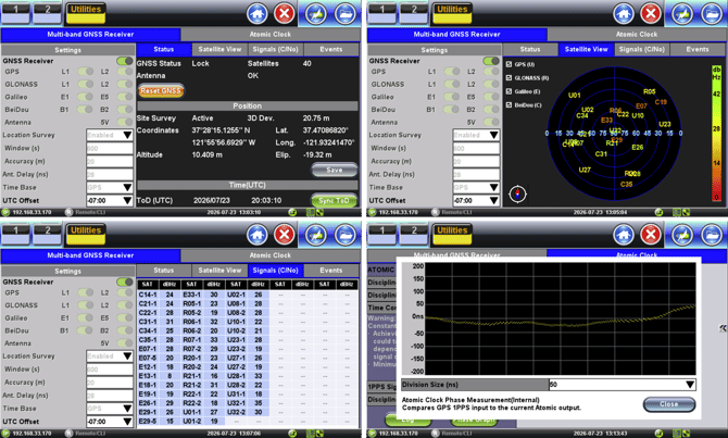
VeEX test sets provide users with extensive GNSS-related status information and graphical views to help assess the overall quality of the resulting 1PPS reference, in the field. These include detailed receiver status, a color-coded satellite view, signal quality (C/No) table for all visible satellites and bands, and an events log. (Instruments with the Atomic Clock option also offer the 1PPS phase alignment graph to assess relative Time Error and stability.) Other vendors, however, may not provide the same level of visibility into GNSS reference quality.
Suggested Reference Materials
- High-Sensitivity GNSS Limitations in RF Perturbed Environments (NATO)
- RF Design Considerations for u-Blox GNSS Receivers
- Maximum Coaxial Cable Length Allowed for GNSS/GPS Antenna Feed
- Measuring Accurate Coaxial Cable Delay, Using Direct Time-of-Flight with CX41 TDR
- GNSS/GPS SkyView Antenna Installation Verification Tool (Actual antenna reception pattern)
- GNSS/GPS Topics in VeEX's Knowledge Base
Related Test Solutions
- TX300s - Portable Multi-Service Test Platform (with optional GNSS receiver)
- RXT-1200 - Advanced Portable Modular Test Platform (with optional GNSS receiver)
- MTTplus - Portable Modular Test Platform (with optional GNSS receiver)
- MTX642 - Dual 400G Portable Test Set (with optional GNSS receiver)
- MTX640 - Dual 100G + 400G Portable Test Set (with optional GNSS receiver)