
Quick introduction on how to use the Terminating Selective (Filtered) G-PON and XGS-PON Optical Power Meter
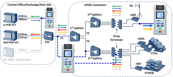
- It terminates the link under test.
- Separates (filters) both signals and measures them separately.
- Supports G, XGS and G+XGS PON modes.
- Optionally, it offers either a Broadband (regular) OPM or a Visual Fault Locator (VFL) port.
- Supports VeEX’s patent pending NoApp™ Cloud Service for quick and easy results transfer, via QR code.
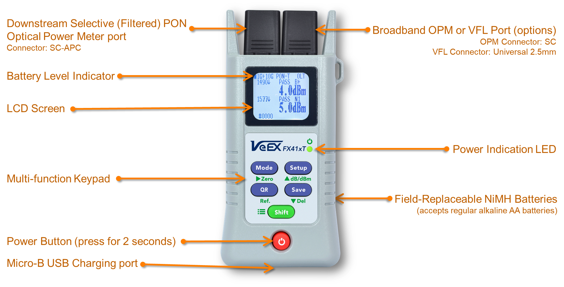
1. The FX41xT G + XGS-PON OPM at a Glance
2. Supported Test Modes
Pressing the Mode button allows users to easily toggle through all the different supported Test Modes offered by the meter.
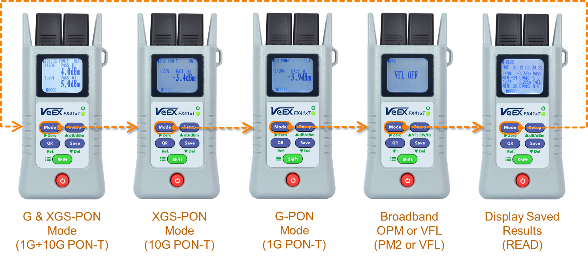
Important: Always clean and inspect all fiber connectors before and after making a connection, or handling them, to prevent contamination and losses.
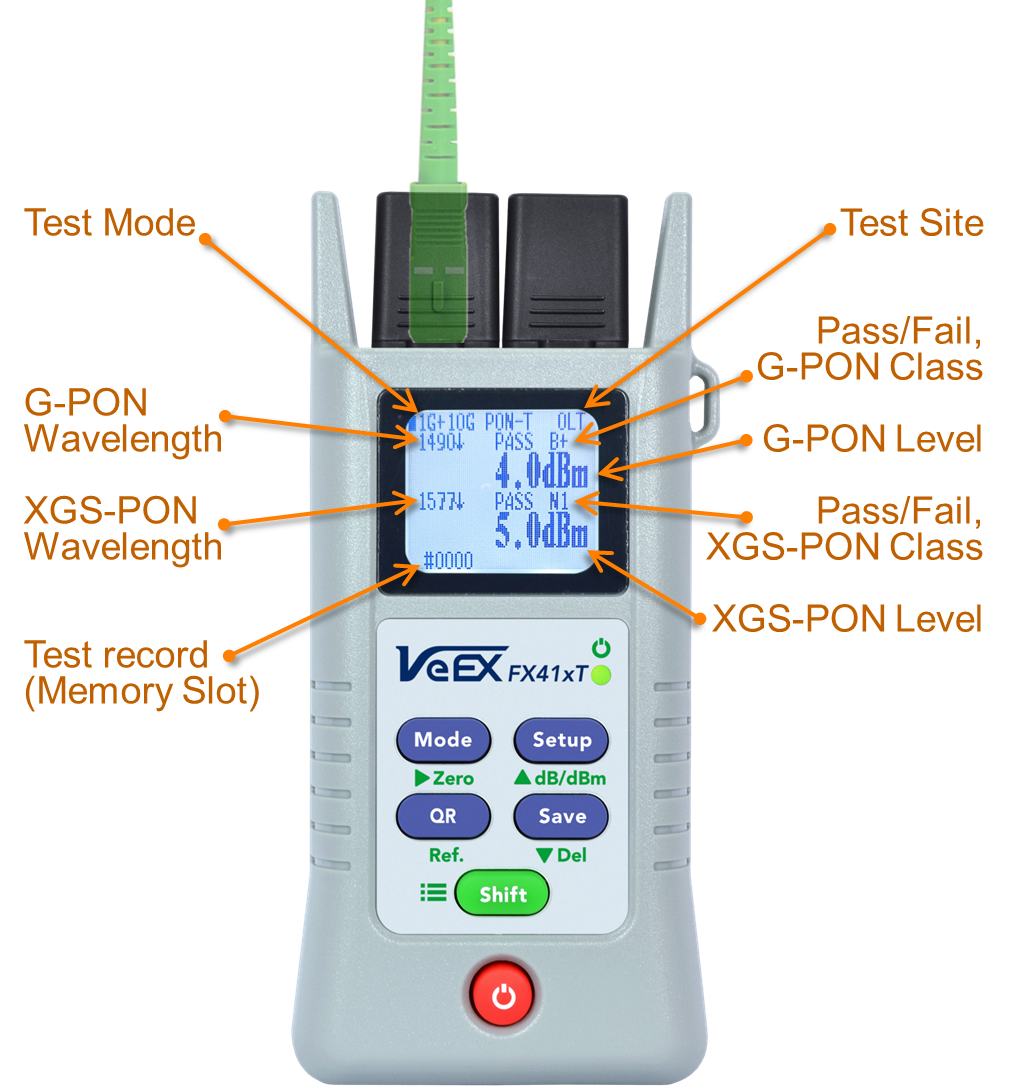
2.1 1G+10G PON-T Mode
Measuring coexisting G-PON (1490 nm) and XGS-PON (1577 nm) downstream signals:
 Use the Mode button to switch to the 1G+10G PON-T Mode.
- Press Setup to select the appropriate Pass/Fail thresholds, based on location.
- Test Sites: OLT, ONT, None, or USER defined.
- Press Shift, then ▲(Setup) to select the appropriate G-PON ODN Class thresholds.
- Press Shift, then ▼(Save) to select the appropriate XGS-PON ODN Class thresholds.
- Close the dust cap, press Shift, then Zero (Mode) to calibrate the zero (dark) reference.
- Connect the fiber under test into the Selective (Filtered) OPM port on the left.
- Press Save to store current measurement results.
- Use the QR button to generate NoApp QR code for current GPON and XGS-PON results transfer.
2.2 10G PON-T Mode
Measuring XGS-PON downstream (1577 nm) signal:
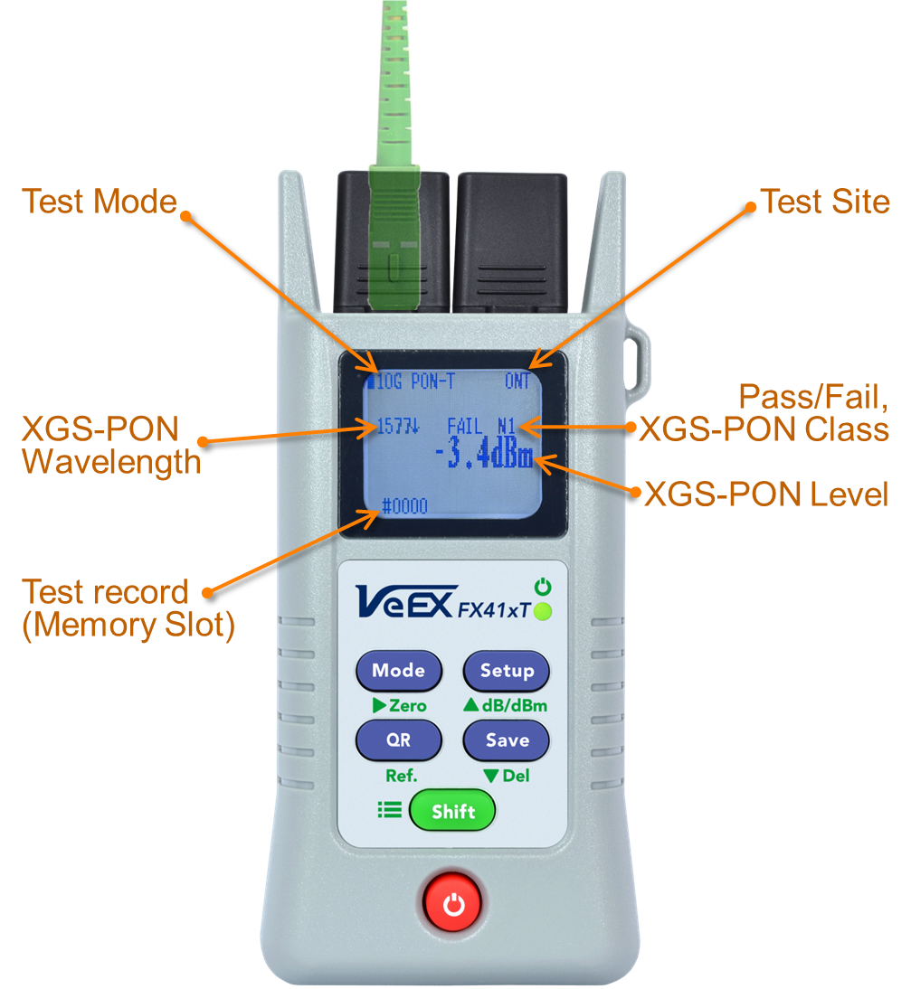 Use the Mode button to switch to the 10G PON-T Mode.
- Press Setup to select the appropriate Pass/Fail thresholds, based on location.
- Test Sites: OLT, ONT, None, or USER defined.
- Press Shift, then ▼(Save) to select the appropriate ODN Class thresholds.
- Close the dust cap, press Shift, then Zero (Mode) to calibrate the zero (dark) reference.
- Connect the fiber under test into the Selective (Filtered) OPM port on the left.
- Press Save to store current XGS-PON result.
- Use the QR button to generate NoApp QR code for current XGS-PON result transfer.
2.3 1G PON-T Mode
Measuring G-PON downstream (1490 nm) signal:
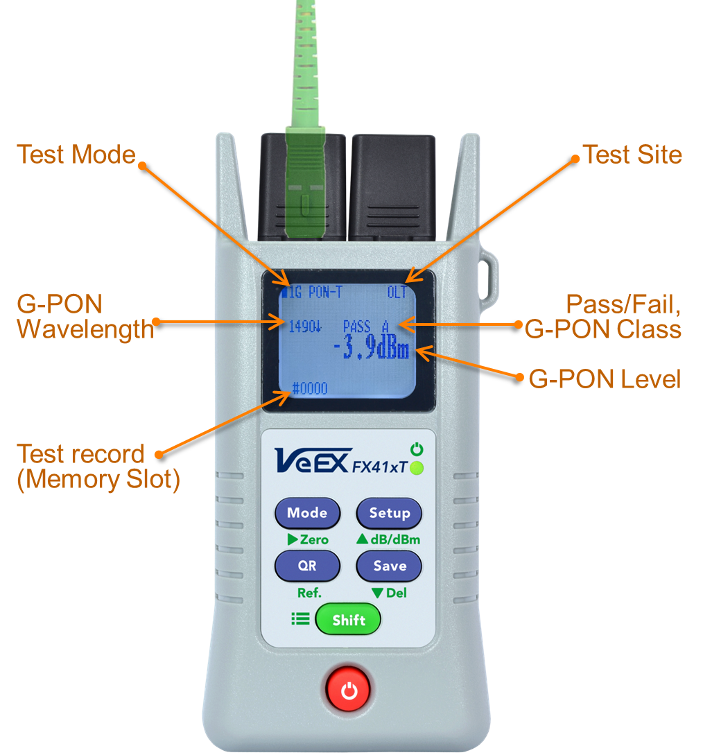 Use the Mode button to switch to the 1G PON-T Mode.
- Press Setup to select the appropriate Pass/Fail thresholds, based on location.
- Test Sites: OLT, ONT, None, or USER defined.
- Press Shift, then ▲(Setup) to select the appropriate ODN Class thresholds.
- Close the dust cap, press Shift, then Zero (Mode) to calibrate the zero (dark) reference.
- Connect the fiber under test into the Selective (Filtered) OPM port on the left.
- Press Save to store current G-PON result.
- Use the QR button to generate NoApp QR code for current G-PON result transfer.
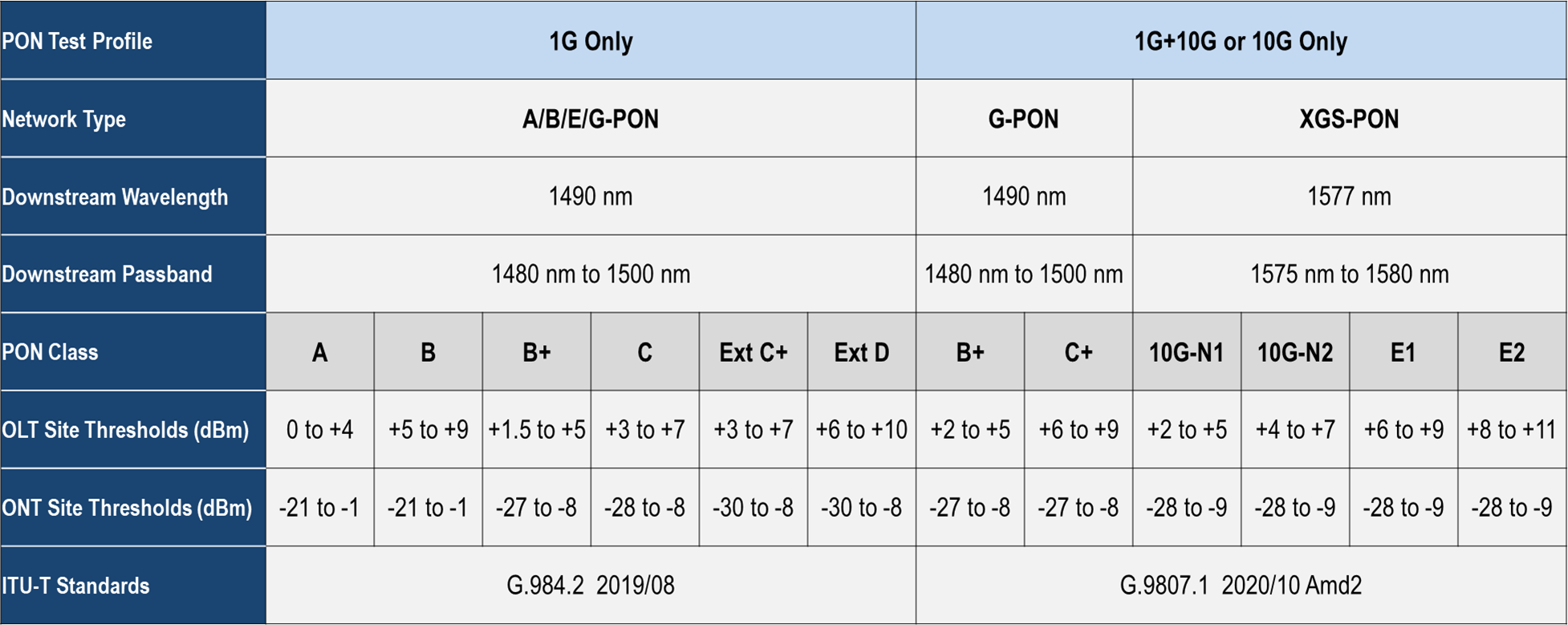
2.4 PON Optical Distribution Network (ODN) Classes
The measurements' standard PASS/FAIL criteria are based on the optical level thresholds that depend on the location (site) in which the measurements were taken, the type of PON network and the expected ODN Class.
2.5 Broadband Optical Power Meter (BB-OPM) Mode
Measuring individual optical signal with the unfiltered (regular) power meter port:
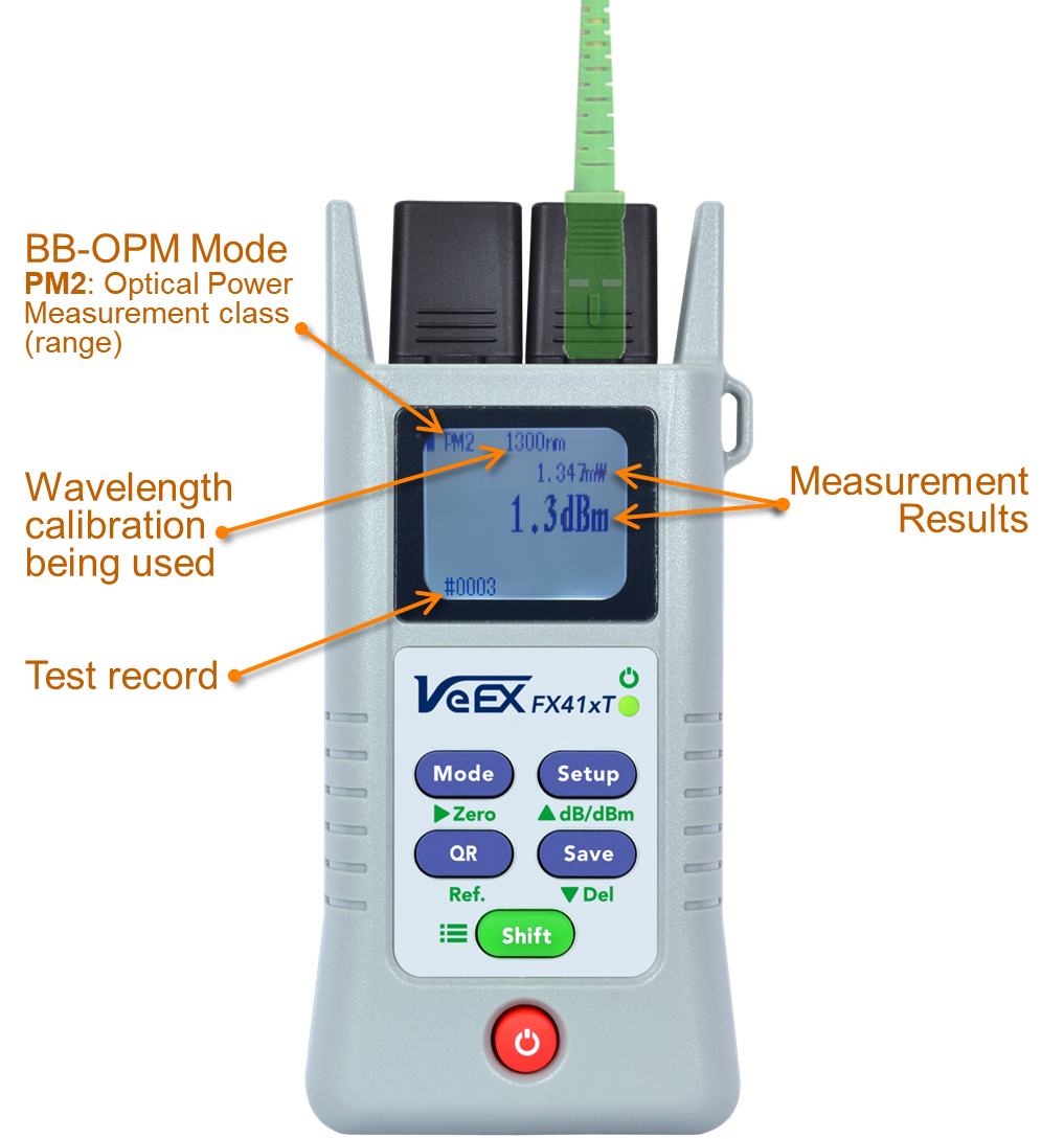 Use the Mode button to switch to the PM2 Broadband OPM Mode (if available).
- PM2 indicates a supported Optical Power Measurement range between -52 dBm and +25 dBm.
- Connect the fiber under test into the BB-OPM port on the right.
- Use the Setup button to select the Wavelength calibration, according to the signal under test.
- Press Shift, then dB/dBm (Setup) to toggle between Power Level (dBm, mW) and Insertion Loss* (dB) measurement modes.
- *Insertion Loss (dB) mode requires referencing first.
- Press Save to store current OPM result.
- Use the QR button to generate NoApp QR code for current OPM reading transfer.
- To Calibrate the OPM’s zero (dark) reference, remove any fiber from the BB-OPM port, close the dust cap, press Shift, then Zero (Mode).
- To set the Reference value for a relative Optical Loss Test, feed the Laser Source (OLS) signal to meter, press Shift, then Ref. (QR). *Insertion Loss (dB) mode requires referencing first.
- Use the Setup button to select the appropriate wavelength under test or set to Automatic.
- Supported calibrated wavelengths are displayed on the top of the screen (multiple options available during the purchasing process).
- A----- indicates Automatic Wavelength Detection, based on VeEX’s Wave ID, if supported by the Laser Source. Once detected, the received wavelength value is displayed and the respective calibration is used for its measurement.
2.6 Visual Fault Locator (VFL) Mode
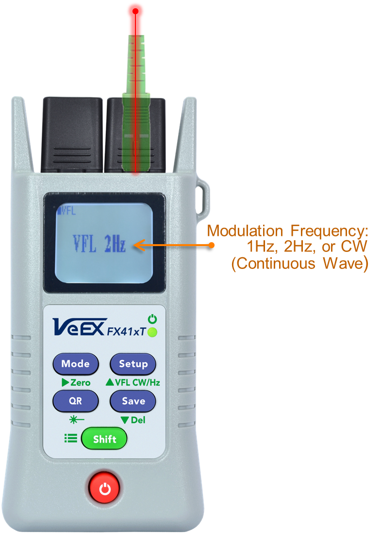 Checking for fiber continuity, macrobends, bad/poor fusion splices, breaks and identifying optical ports:
- Use the Mode button to switch to the VFL Mode (if available).
- Connect the fiber under test into the VFL port on the right.
- Press the Laser (QR) button to turn the red (655 nm) laser source ON and OFF.
- When the laser is ON, press VFL CW/Hz (Setup) to select between Continuous Wave and intermittent VFL frequencies.
Note: VFL is a factory-built option, mutually exclusive with the Broadband OPM option.
Due to its relatively high optical output power, you should never look at the output of the VFL port or fiber connector directly.
2.7 Read (Recall) Saved Results Mode
To view previously saved test results:
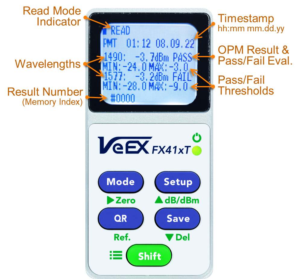 Press Mode button to switch to the Read Results Mode.
- Press ▲(Setup) to increase memory slot index (browse different saved test results).
- Press ▼(Save) to decrease memory slot index (browse different saved test results).
- Press Shift, then Del (Save) to delete the test record currently displayed.
- Use the QR button to generate NoApp QR code for current OPM reading transfer.
3. User Defined Threshold
To editing the USER customizable MAX and MIN power level thresholds:
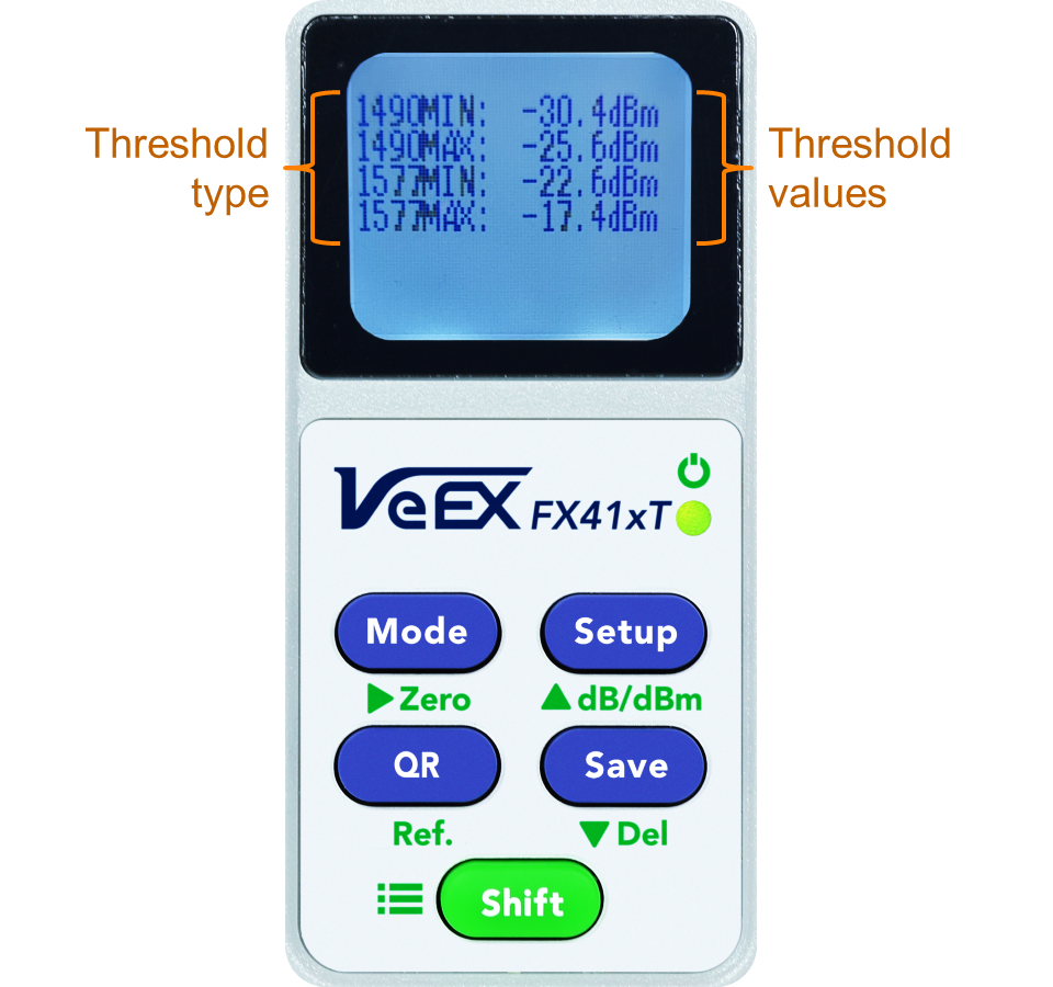 In PON Measurement mode, press and hold the Setup button, to display limits.
- The selected sign or digit will flash.
- Press ▲(Setup) to increase number or change sign.
- Press ▼(Save) to decrease number or change sign.
- Press
 (Mode) to select the next digit or sign.
- Each supported wavelength has MINimum and MAXimum Thresholds.
- Results must be within these ranges to PASS.
- Press and hold the Setup button to save settings and return to previous screen.
4. Setting Time & Date
To adjust the Meter’s internal Real Time Clock (RTC):
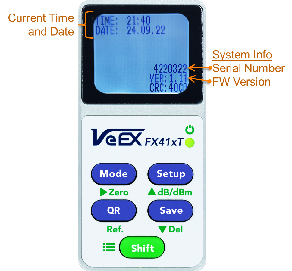 Press and hold the Shift button (outside of Read Results mode), to adjust the time and date settings.
- The selected number will flash.
- Press ▲(Setup) to increase number.
- Press ▼(Save) to decrease number.
- Press (Mode) to select the next number.
- Press and hold the Shift button to save settings and return to previous screen.
5. NoApp™ QR Results Transfer & R-Server™
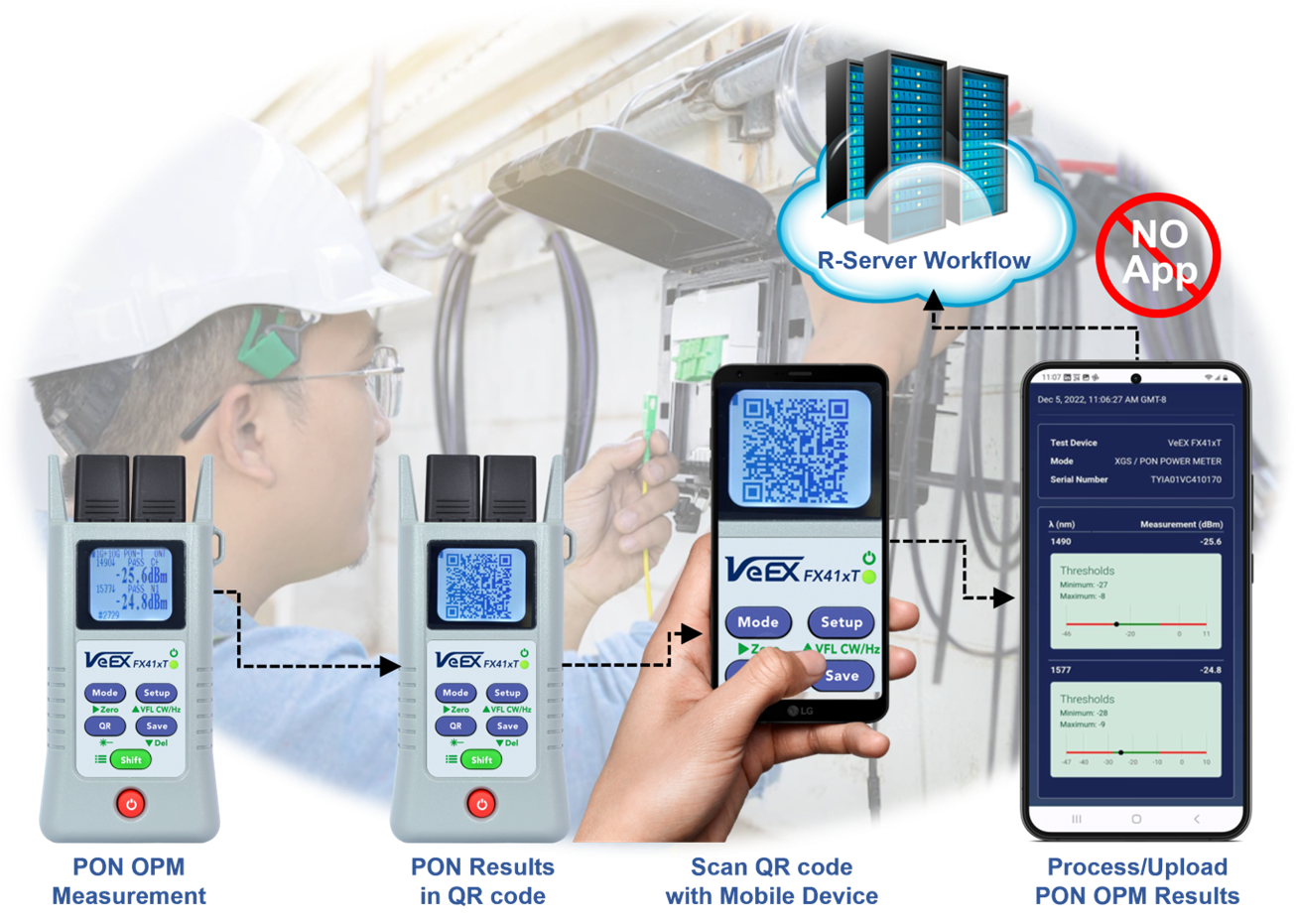
VeEX's patent pending simple NoApp cloud service offers a quick and simple way to transfer measurement results, generate, upload & share Test Reports. Just scan the QR code on the screen.
-
The secure NoApp™ Cloud service offers test results transfer to smartphones, tablets or PC/MAC, without any setup, pairing, connection or software (app) to install. No software updates required - this web application is always up to date.
-
Augments test results with GPS coordinates, job information, comments, pictures, etc.
-
Compatible with VeSion® R-Server (R-Server account required).
To generate the QR code for the current test results:
- Press the QR button to display the NoApp™ QR Code for the current measurement.
-
Use a smartphone or tablet camera to scan it.
-
Press the QR button again to return to the Results screen.
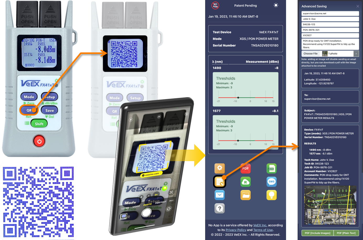
Scan the sample QR code above, to see an example.
For More Information
- FX41xT Product Website and Resources
- FX41xT PON Optical Power Meter User Manual
- PON Glossary
- Contact Us
Related Test Solutions
- FX81T 1G/10G Pass-Through PON Optical Power Meter
- FX120-Lite XGS-PON Analyzer
- FX120 XGS-PON Analyzer & Multi-Gigabit Internet QoE
- NoApp™ Cloud Service Guide
- VeSion© R-Server Cloud-Based Workflow and Asset Management